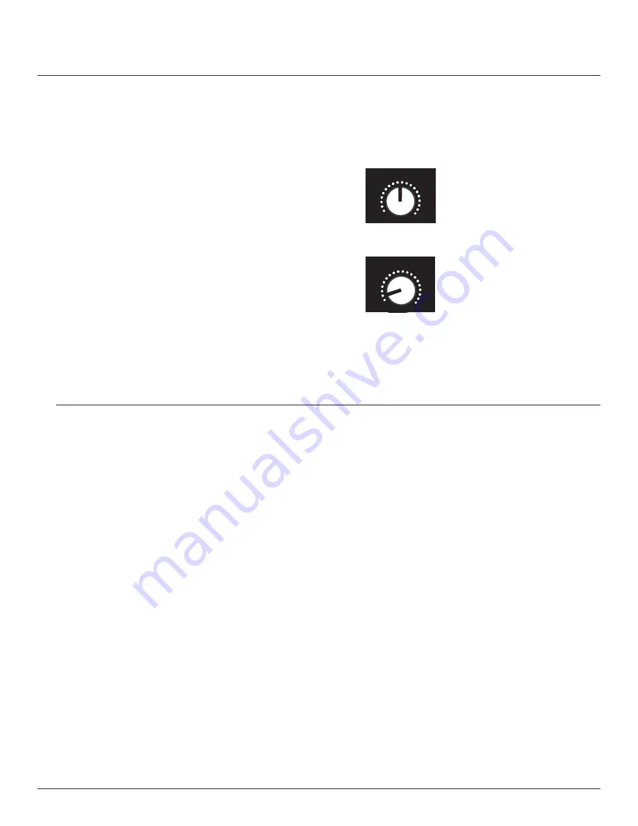
The following levels should be used as a reference if you know the maximum output in dBu of the source
connected to the system’s input. For each position stated below there is an input signal level in dBu that is
required to deliver absolute maximum output of the system.
LINE
Level position
Input level required to deliver maximum output
Full “on”
+10 dBu
3 o’clock
+12 dBu
12 o’clock
+17 dBu
9 o’clock
+28 dBu
MIC
Level position
Input level required to deliver maximum output
Full “on”
-25 dBu
3 o’clock
-23 dBu
12 o’clock
-18 dBu
9 o’clock
-7 dBu
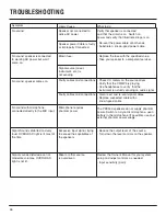
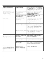
Only a properly setup system will guarantee maximum performance with a minimum of distortion and feedback.
(This is as true for self powered systems as it is for passive systems). An easy to rule to follow is:” Everything
should clip at once.”
Following these simple steps will ensure you are getting the optimum performance out of your complete system.
1. Once the source has been connected to the input of your mixer, adjust the input sensitivity (or trim) so
that the highest input levels are set to just before clip (or when the input LED just starts to flicker).
2. Position the channel fader for that input to 0 dB.
3. Position the Master output fader to 0 dB.
4. With the “Mic/Line” button set to “Line” (because the system is receiving a line level signal, or
commonly called a +4 dB signal), set the “Level” control to the 12 o’clock position, and adjust until the
“overload” LED just begins to flicker.
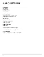
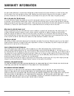
For in depth articles related to gain structure please refer the website where you can find the JBL Sound System
Design Reference Manual; http://www.jblpro.com/pub/technote/ssdm_99.pdf
+17
+12
+10
+28
0
-18
-23
-25
-7
0
SETTING THE GAIN
19
Summary of Contents for PRX512M
Page 1: ...P R X 5 1 2 M P R X 5 1 5 P R X 5 3 5 P R X 5 2 5 P R X 5 1 8 S U s e r s G u i d e ...
Page 2: ...2 ...
Page 6: ...6 ...
Page 8: ...8 ...
Page 15: ...15 Notes ...
Page 30: ...30 ...
Page 31: ...31 ...


