background image

8

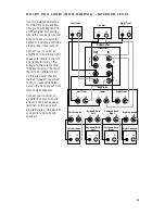
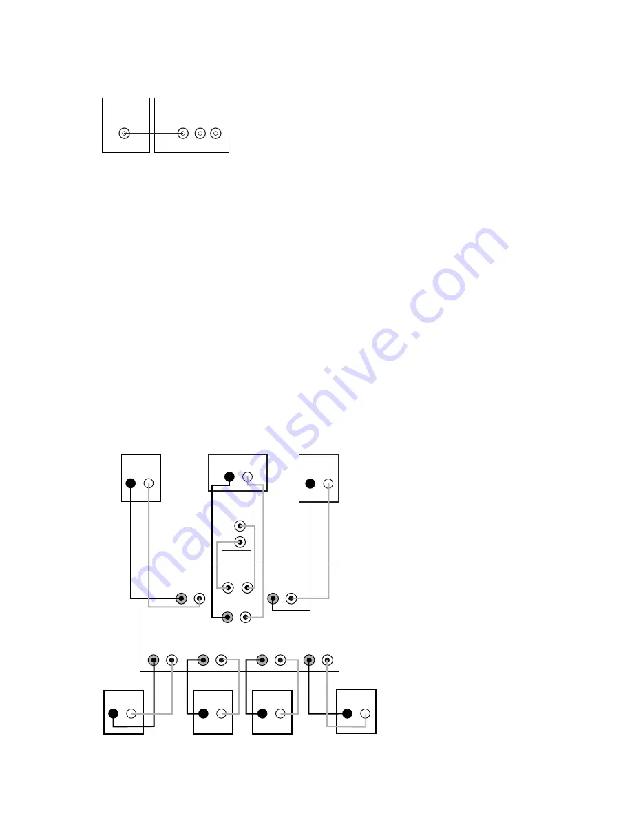
DOLBY PRO LOGIC* (NON-DIGITAL) – LINE LEVEL

Use this installation method
for Dolby Pro Logic applica-
tions (not Dolby Digital, DTS
or other digital processing),
where the receiver/proces-
sor is equipped with a sub-
woofer output, or a volume-
controlled preamp (line-)
level output:

Use RCA-type interconnects
to connect the line-level 
subwoofer outputs on your
receiver or amplifier to the
line-level inputs on the sub-
woofer. IMPORTANT: Do not
use the LFE input on the sub-
woofer with Dolby Pro Logic
processors. 

NOTE: If your receiver or
amplifier only has one sub-
woofer output jack, then you
will need to use a Y-connec-
tor (not included). Plug the
male end of the Y-connector
into your receiver or ampli-
fier’s subwoofer output jack,
and connect each of the two
female ends to separate
RCA-type interconnects.
Finally, plug the RCA-type
interconnects into the line-
level inputs on the sub-
woofer.

Connect each speaker to 
the corresponding speaker
terminals on your receiver 
or amplifier.

Make sure your receiver or
processor is correctly con-
figured to indicate that the
subwoofer is “On.”

Note for advanced users: If
your receiver/processor has
a built-in low-pass crossover
filter for the subwoofer out-
put, you may use the LFE
input to bypass the sub-
woofer’s internal crossover.

Use this installation method
for Dolby Digital, DTS or
other digital surround
processors: 

Use the line-level input jack
marked “LFE” for the Low-
Frequency Effects channel.

Connect this jack to the LFE
output or subwoofer output 
on your receiver or amplifier.
Connect each speaker to the
corresponding speaker 
terminals on your receiver 
or amplifier.

Make sure that you have
configured your surround
sound processor for “Sub-
woofer On.” Also configure
your receiver for 5.1-, 6.1- or

7.1-channel operation as
appropriate. The front left,
front right, center and rear
speakers should all be set to
“Small.” If your receiver
allows you to set the cross-
over frequency between the
subwoofer and the main
speakers, select 120Hz or the
setting that is the closest fre-
quency below it.

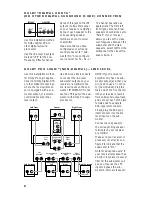
DOLBY* DIGITAL OR DTS

®

(OR OTHER DIGITAL SURROUND MODE) CONNECTION

LINE

LEVEL

IN

LFE       L       R

LFE OUT

SUBWOOFER

RECEIVER

–       +

–       +

–       +

–       +

–       +

–       +

–       +

–       +

–       +

Receiver

Subwoofer 

Out

Left

Front

Left

Surround

–       +

Right

Front

Right

Surround

Subwoofer

R        L

Center

Surround Back

Left

Line-

Level In

Right Surround

Right Front

Left Surround

Left Front

Center

L

–       +

Surround Back

Left

–       +

–       +

Surround Back

Right

–       +

Surround Back

Right

Summary of Contents for SCS200.7

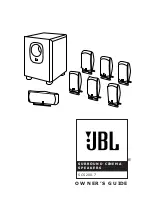
Page 1: ...SCS200 7 SURROUND CINEMA SPEAKERS OWNER S GUIDE...

Page 2: ...onductors location of antenna discharge unit connection to grounding electrodes and require ments for the grounding electrode See Figure A 18 An outside antenna system should not be located in the vic...

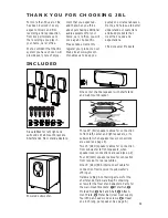
Page 3: ...ix satellites for left right and surrounds Wall mount brackets Shelf stands Floor stand adaptors One center channel speaker with shelf stand and wall mount bracket Powered subwoofer Three 20 6m speake...

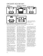
Page 4: ...and a single surround back speaker should be placed on the wall behind the listening position In 7 1 channel applications place two of the surround speakers in the side positions and place the two su...

Page 5: ...ilitate installation with a variety of general purpose floor stands available from many manufacturers Since different stands will have different weight capacities and stability characteristics it is t...

Page 6: ...d Shaft into the Threaded Insert on the back of the Satellite Speaker until it is fully seated in the Threaded Insert but do not tighten as you might dislodge the Threaded Insert Such damage would not...

Page 7: ...r use with banana type connectors To comply with European CE certification these holes are blocked with plastic inserts at the point of manufacture To use banana type connectors requires the removal o...

Page 8: ...s If your receiver processor has a built in low pass crossover filter for the subwoofer out put you may use the LFE input to bypass the sub woofer s internal crossover Use this installation method for...

Page 9: ...ked Speaker Level In Connect the left and right terminals on the subwoofer that are marked Speaker Level Out to the corresponding termi nals on the back of your front left and right speakers Connect y...

Page 10: ...tch marked Power to the On position to use the SUB200 subwoofer If you will be away from home for an extended period of time or if the subwoofer will not be used switch the Master Power switch to the...

Page 11: ...er processor is set in one of the Dolby Digital or DTS modes make sure the receiver processor is configured so that the center speaker is enabled If the system plays at low volumes but shuts off as vo...

Page 12: ...z 6dB Woofer 8 200mm Enclosure Bass reflex Dimensions H x W x D including feet 16 1 4 x 11 x 13 3 4 413mm x 279mm x 349mm Weight 28 lb 12 7kg SPECIFICATIONS All features and specifications are subject...

Reviews: