JBL Synthesis
Installation
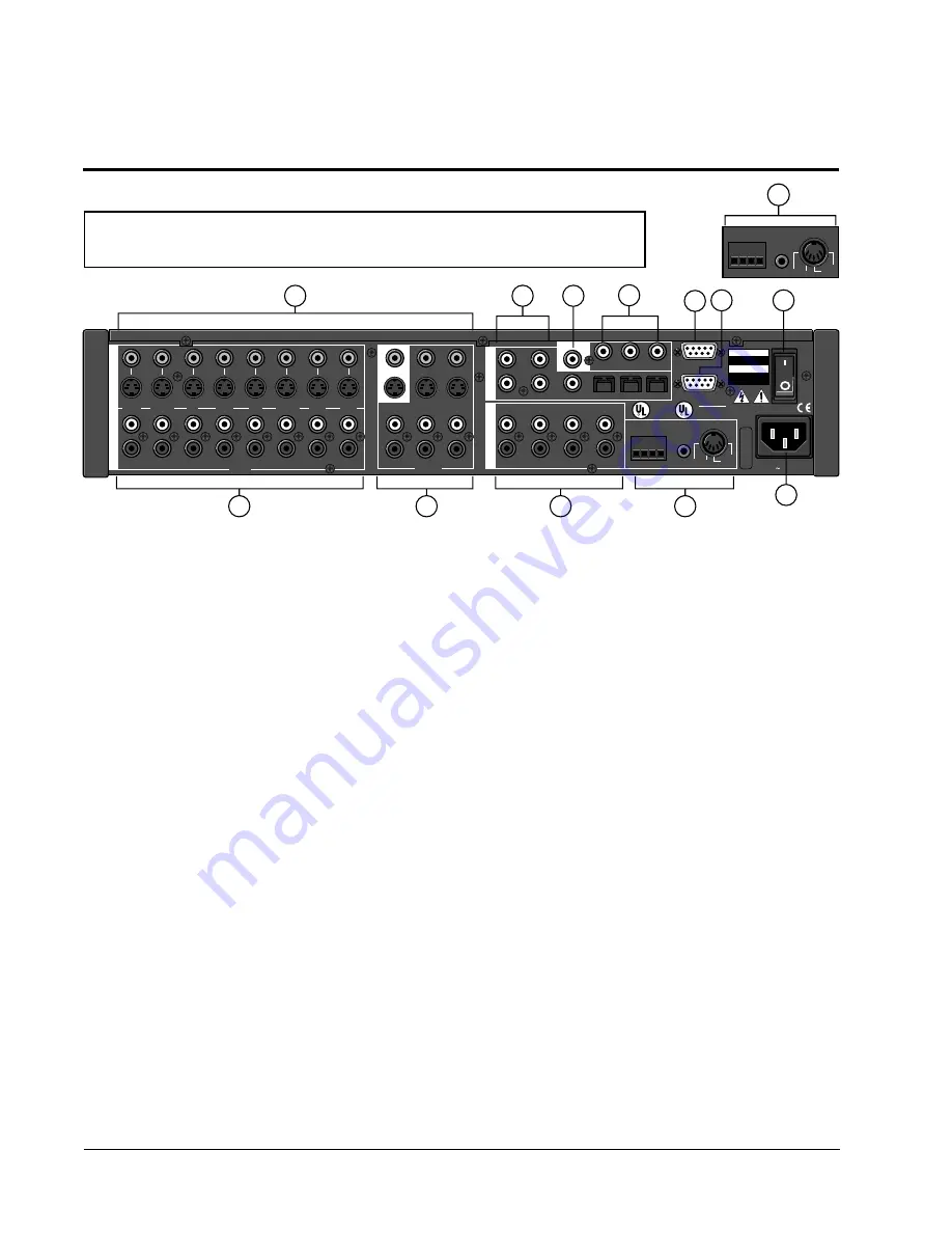
The Rear Panel
CAUTION: Never make or break any connections to the SDP-3 with the rear-panel power ON.
Make sure any associated amplifiers are turned off before turning this master power switch
on or off.
1 AUDIO INPUTS
8 stereo analog audio inputs
switched with corresponding
video inputs and fed to the
Monitor outputs. Inputs are
nominally labeled as origi-
nating from an audio tape
player, tuner, CD player, an
unspecified auxiliary source,
a TV tuner, a Laser or Video
Disc player, a DVD player,
and a VCR.
2 ZONE2 and RECORD
3 pairs of stereo audio out-
puts and 2 video outputs sup-
ply the same signal accord-
ing to the Record/Zone 2 in-
put selection. Zone 2 output
levels can be controlled in-
dependently for use with
amplifiers and speakers in
another room. These out-
puts are muted in Standby.
3 MAIN OUTPUTS
3 stereo amplifier outputs
provided for front, side and
rear speakers. Single out-
puts are provided for the cen-
ter speaker and the
subwoofer. These outputs
are muted in Standby.
4 IR Input, PWR and
PGM TRIGGERS
The IR input is an 1/8" mono
connector for input of IR data
from any industry-standard
IR source. Data is retransmit-
ted by an IR LED mounted
near the front panel IR re-
ceiver.
2 trigger outputs are pro-
vided on 4-pin removable
screw terminals, and a 5-pin
DIN connector, as shown in
the expanded illustration
above. The PWR trigger is
high when the SDP-3 is on,
low in standby or when the
unit is off. The PGM trigger
can be enabled (high) or
disabled (low) for specific
surround modes in the Effect
Adjust menu. High is indi-
cated by 5VDC or
+12VDC, selectable via an
internal jumper. (Factory
configuration is +5V.)
5 VIDEO INPUTS and
OUTPUTS
8 video input sources se-
lected based on selections
made in the INPUT CONFIG
menu and fed to the selected
monitor output jack. Record
output jacks can be selected
independently.
RCA (composite) and
S-video connectors are pro-
vided for monitor and record.
If an S-video input is used,
both S-video and composite
are available at each output.
If the video input is compos-
ite, only composite is avail-
able at each output. The
monitor output incorporates
the on-screen video overlay.
Unless RECORD is en-
abled, the record output fol-
lows the monitor output se-
lection without the on-screen
display feature. All three out-
puts are blanked in Standby.
6 S/PDIF INPUTS
5 coaxial RCA connectors
and 3 optical connectors for
digital audio input.
7 S/PDIF OUTPUT
Coaxial digital audio output
for digital-to-digital audio re-
cording. Any digital audio
output (coaxial or optical)
selected for Record or Zone
2 will also be sent directly to
this output.
8 EXPANSION PORTS
3 coaxial digital audio inputs
capable of accepting stereo
PCM signals up to 24-bit/
96kHz. Note: These inputs
completely bypass the digital
signal processing path, in-
cluding the crossovers and
effects, passing the audio
signal directly to the following
channels: A to the L and R
Front channels, B to the Cen-
ter and Subwoofer channels
and C to the L and R Sur-
round channels.
9 RS 232
Reserved for future control
and communication options.
10 RS 232
Serial port connector for au-
tomation and control sys-
tems.
11 Power On/Off
Master power switch discon-
nects the AC Mains. This
switch is intended to be left
On during regular use.
Whenever cables are con-
nected or disconnected, or
when the unit is not going to
be used for an extended pe-
riod of time, this switch
should be set to Off.
12 POWER
AC power connector: 3-wire,
10 Amp, IEC 320.
AUDIO
EXPANSION PORTS
L
R
L
R
A
B
C
L
R
L
R
L
R
SUBWOOFER
TAPE
TUNER
CD
AUX
TV
V-DISC
DVD
VCR
AUDIO
INPUT
TRIGGERS
GND
S
PGM
PWR
IR IN
TRIGGERS
PGM GND PWR
R
C
R
LISTED AUDIO
EQUIPMENT
7D77
E172268
MAIN OUTPUTS
REAR
ZONE 2
RECORD 1 RECORD 2
SIDE
CENTER
FRONT
1
2
3
S/PDIF INTPUTS
1
3
2
4
5
S/PDIF OUT
RISK OF ELECTRIC SHOCK
DO NOT OPEN
RISQUE DE CHOC
ELECTRIQUE
NE PAS OUVRIR
CAUTION
ATTENTION
RS 232
100-240V
50-60 Hz, 35W
SDP-3
JBL Synthesis, INC.
ASSEMBLED IN U.S.A.
OUTPUT
MONITOR
S-VIDEO
VIDEO
1
3
2
4
12
5
6
7
8
11
10
9
TRIGGERS
TRIGGERS
GND
PGM
PWR
IR IN
PGM GND PWR
4
2


