background image

7

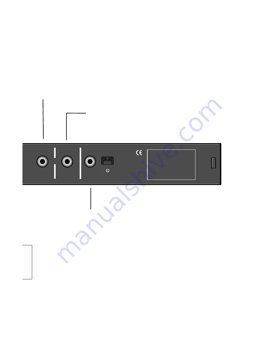
Rear Panel

OUTPUT

Connect this S/PDIF output to SDP-2
digital input COAX1 with a 75

coaxial

cable.

S/PDIF INPUTS

Connect this input to the laser disc player’s NON-
AC-3

®

RF digital output using the appropriate 75

coaxial cable.

Because you can switch between these inputs
from the front panel, you may use both; which
gives you an extra digital input.

ad-

esis

the

e laser disc player’s AC-3

®

/RF

xial cable. Keep this cable as

nimize RF interference.  

stant
n)

able)

RF IN

S/PDIF INPUTS

THIS DEVICE COMPLIES WITH PART 15

OF THE FCC RULES.

OPERATION IS SUBJECT TO THE

FOLLOWING TWO CONDITIONS:

(1) THIS DEVICE MAY NOT CAUSE

HARMFUL INTERFERENCE, AND

(2) THIS DEVICE MUST ACCEPT ANY

INTERFERENCE RECEIVED,

INCLUDING INTERFERENCE THAT MAY

CAUSE UNDESIRED OPERATION.

AC-3

®

COAX

S/PDIF

OPTICAL

OUTPUT

Summary of Contents for SDP-RFD

Page 1: ...SDP RFD AC 3 RF DEMODULATOR 120V 230V INSTALLATION TECHNICAL MANUAL ...

Page 2: ... kind on the unit This product is equipped with a 3 wire grounding type plug This is a safety feature and should not be defeated To prevent shock or fire hazard do not expose the unit to rain or moisture or operate it where it will be exposed to water Do not attempt to operate the unit if it has been dropped damaged exposed to liquids or if it exhibits a distinct change in performance indicating t...

Page 3: ... AC 3 signal quality By placing the req uisite demodulation circuitry in its own enclosure with dedicated power supplies and grounding the potential to degrade digital to analog conversion and analog audio signals within the preamp processor is eliminated The SDP RFD Demodulator incorpo rates fully automated intelligent switching between S PDIF and AC 3 RF inputs meaning that any laser disc will b...

Page 4: ...present the LED will rema POWER This LED will light whenever power to the unit is supplied and enabled POWER RF TIMING LOCK AC 3 RF DEMODULATOR RF TIMING 3 position switch which minimizes signal errors providing optimal timing for specific brands of laser disc players Recommended Settings Advance Panasonic Runco Retard Denon Normal All others ...

Page 5: ...ignal When no such signal ain off and the INPUT SELECT LED will light INPUT SELECT 2 position switch for selection of the type of NON AC 3 RF digital output you are using from your laser disc player ADVANCE RETARD NORMAL OPTICAL COAX INPUT SELECT ...

Page 6: ...er This set up allows use of a switched outlet or continuous power As power consumption and heat generation are both minimal this will not harm the SDP RFD LOOP THRU Allows the hook up and power cycling of a ditional components such as the Synthe S Series of power amplifiers Refer to DIN configuration diagram below RF IN Connect this input to the output with a 75Ω coax short as possible to min 1 G...

Page 7: ...panel you may use both which gives you an extra digital input ad esis the e laser disc player s AC 3 RF xial cable Keep this cable as nimize RF interference stant n able RF IN S PDIF INPUTS THIS DEVICE COMPLIES WITH PART 15 OF THE FCC RULES OPERATION IS SUBJECT TO THE FOLLOWING TWO CONDITIONS 1 THIS DEVICE MAY NOT CAUSE HARMFUL INTERFERENCE AND 2 THIS DEVICE MUST ACCEPT ANY INTERFERENCE RECEIVED I...

Page 8: ... RECORD OUTPUTS VIDEO OUT INPUTS MONITOR RECORD POWER 9V 1A 50 60Hz USE SYNTHESIS MSA AC ADAPTER PWR CTL INPUT LOOP THRU PWR CTL to other components such as amplifiers ANALOG AUDIO OUT L R LASER DISC PLAYER SDP RFD AC 3 RF DEMODULATOR SDP 2 75 ohm COA as short as po COAX Audio cable ...

Page 9: ...OPTICAL 1 2 RF IN S PDIF INPUTS AC 3 COAX S PDIF OPTICAL OUTPUT AC 3 RF OUTPUT DIGITAL OUTPUT COAX OPTICAL TOSLINK OR AX cable ossible 75 ohm COAX cable COAX 1 digital input Default input for V DISC 5 pin DIN cable not included 75 ohm COAX cable Optical cable Use one or the other Most players have only one ...

Page 10: ...This allows the SDP RFD to power on and off with the SDP 2 If this con nection is not made the SDP RFD will turn on whenever its AC adapter is supplied power Optional Connect any additional components which allow remote turn on such as Synthesis S Series of power amplifiers to the SDP RFD rear panel PWR CTL LOOP THRU connector Connect the AC adapter provided to the POWER jack Once the SDP RFD is p...

Page 11: ...ing Advance Retard Normal Input Select Optical COAX Connectors Inputs 4 2 RCA COAX 1 TOSLINK Optical 1 5 pin DIN PWR CTL Outputs 2 1 RCA COAX 1 5 pin DIN PWR CTL Thru Power connector 2 5mm 9VAC 1A General Dimensions 17 0 X x 1 75 H x 4 D Weight 2 4 lbs net 4 4 lbs shipping Power Requirements 120VAC 60Hz or 230VAC 50Hz Use JBL MSA AC Power Adapter All specifications subject to change without notice...

Page 12: ...en Michaelsen JBL Europe A S Birkerød DENMARK 2 97 JBL Synthesis System Owner s Manual 1997 Harman Consumer Group JBL and Synthesis are registered trademarks of JBL Incorporated All Rights Reserved Manual Designed by Harman Consumer Group Design Production Center Woodbury New York JBL Consumer Products Inc 80 Crossways Park West Woodbury NY 11797 516 496 3400 8500 Balboa Boulevard Northridge CA 91...

Reviews: