


01 - Machine
03 - Safety
24 - Risk Assessment
01 - 11
9813/4250-6
01 - 11
24 - Risk Assessment
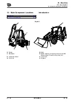
Introduction
It is the responsibility of the competent people that
plan the work and operate the machine to make a
judgement about the safe use of the machine, they
must take into account the specific application and
conditions of use at the time.
It is essential that a risk assessment of the work to be
done is completed and that the operator obeys any
safety precautions that the assessment identifies.
If you are unsure of the suitability of the machine for
a specific task, contact your JCB dealer who will be
pleased to advise you.
The following considerations are intended as
suggestions of some of the factors to be taken into
account when a risk assessment is made. Other
factors may need to be considered.
A good risk assessment depends on the training and
experience of the operator. Do not put your life or the
lives of others at risk.
Personnel
•
Are all persons who will take part in the
operation sufficiently trained, experienced and
competent? Are they fit and sufficiently rested?
A sick or tired operator is a dangerous operator.
•
Is supervision needed? Is the supervisor
sufficiently trained and experienced?
•
As well as the machine operator, are any
assistants or lookouts needed?
The Machine
•
Is it in good working order?
•
Have any reported defects been corrected?
•
Have the daily checks been carried out?
•
Are the tyres still at the correct pressure and
in good condition and is there sufficient fuel to
complete the job (if applicable)?
The Load
•
How heavy is it? Is it within the capabilities of
the machine?
•
How bulky is it? The greater the surface area,
the more affected it will be by wind speeds.
•
Is it an awkward shape? How is the weight
distributed? Uneven loads are more difficult to
handle.
•
Is there a possibility of the load shifting while
being moved?
Loading/Unloading Area
•
Is it level? Any slope of more than 2.5% (1 in
40) must be carefully considered.
•
Is more than one direction of approach to the
load possible? Approaching across the slope
must be avoided, if possible.
•
Is the ground solid? Will it support the weight of
the machine when loaded?
•
How rough is the ground? Are there any
sharp projections which could cause damage,
particularly to the tyres?
•
Are there any obstacles or hazards in the area,
for example, debris, excavations, manhole
covers, power lines?
•
Is the space sufficient for safe manoeuvring?
•
Are any other machines or persons likely to be
in or to enter the area while operations are in
progress?
The Route to be Travelled
•
How solid is the ground, will it provide sufficient
traction and braking? Soft ground will affect the
stability of the machine and this must be taken
into account.
•
How steep are any slopes, up/down/across?
A cross slope is particularly hazardous, is it
possible to detour to avoid them?
Weather
•
How windy is it? High wind will adversely affect
the stability of a loaded machine, particularly if
the load is bulky.
•
Is it raining or is rain likely? The ground that
was solid and smooth when dry will become
uneven and slippery when wet, and it will not
give the same conditions for traction, steering
or braking.
Summary of Contents for 3CXG
Page 2: ...9813 4250 6 Notes Find manuals at https best manuals com...
Page 4: ...Notes 9813 4250 6 Find manuals at https best manuals com...
Page 8: ...Notes 01 2 9813 4250 6 01 2 Find manuals at https best manuals com...
Page 22: ...Notes 01 16 9813 4250 6 01 16...
Page 26: ...Notes 01 20 9813 4250 6 01 20...
Page 32: ...Notes 01 26 9813 4250 6 01 26...
Page 36: ...Notes 9813 4250 6 2017 11 23...
Page 38: ...Notes 03 2 9813 4250 6 03 2...
Page 51: ...This as a preview PDF file from best manuals com Download full PDF manual at best manuals com...


