background image

 03 - Attachments, Couplings and Load Handling

 00 - Attachments

 00 - General

03 - 3

9813/4250-6

03 - 3

00 - General

Introduction 

......................................................

 03-3

Health and Safety 

...........................................

 03-4

Lubricate 

..........................................................
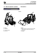
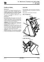
 03-4

Introduction

A wide range of optional attachments are available

to increase the versatility of your machine. Only JCB

approved  attachments  are  recommended  for  use

with your machine. Consult your JCB Distributor for

the full list of approved attachments available.

Some  attachments  are  supplied  complete  with

instructions  on  safety,  installing  and  removing,

operation  and  maintenance.  Read  and  fully

understand the information before fitting, using and

servicing the attachment. If there is anything you do

not understand, ask your JCB Distributor.

Before  using  any  attachment,  read  Working  With

The Machine in the Operator Manual and consider

how  the  attachment  is  going  to  affect  operational

safety.  With  the  attachment  installed,  there  may

be  changes  in  the  machine's  centre  of  gravity  or

overall dimensions. This could have an effect on, for

example, machine stability, the gradients on which it

is safe to operate or the safe distance from power

lines.

Practice using attachments off the job before working

with them for the first time.

JCB  attachments  are  designed  and  manufactured

specifically to suit the machine's hydraulic system,

mounting arrangements and safe load requirements.

Attachments  which  are  not  designed  for  use  with

this machine may cause damage and create safety

hazards for which JCB cannot be held responsible.

In  addition  the  machine's  warranty  and  any  other

legislative compliance may be affected by the use of

non JCB approved attachments.

If your machine needs the hydraulic system adapting

to  facilitate  the  use  of  auxiliary  attachments,  you

must consult your distributor. Only suitably qualified

personnel must reroute hydraulic hoses.

All  optional  attachments  will  have  limits  on  their

operation. i.e. lifting capacity, speeds, hydraulic flow

rates,  etc.  Always  check  in  the  literature  supplied

with the attachment or in the Specification section of

this manual. Some specification limits may also be

displayed on the attachments Data/Rating Plate.

Important: Do not operate or work with attachments

until the machine hydraulic oil has reached its normal

working temperature.

Summary of Contents for 3CXG

Page 1: ...al You must understand and follow the instructions in the Operator s Manual If you do not understand anything ask your employer or JCB dealer to explain it Do not operate the machine without an Operat...

Page 2: ...9813 4250 6 Notes Find manuals at https best manuals com...

Page 3: ...3 4250 6 SERVICE MANUAL Volume 1 3CXG EN 9813 4250 SERVICE MANUAL Volume 2 3CXG EN 9813 4250 SERVICE MANUAL Volume 3 3CXG EN 9813 4250 SERVICE MANUAL Volume 4 3CXG EN 9813 4250 Find manuals at https b...

Page 4: ...Notes 9813 4250 6 Find manuals at https best manuals com...

Page 5: ...ety 01 6 01 03 18 Operating Safety 01 8 01 03 21 Worksite Safety 01 10 01 03 24 Risk Assessment 01 11 01 03 27 Maintenance Positions 01 12 01 06 About this Manual 01 06 03 Model and Serial Number 01 1...

Page 6: ...9813 4250 6 2018 02 05 Acronyms Glossary FOPS Falling Object Protective Structure PIL Parts Identification List ROPS Roll Over Protective Structure Find manuals at https best manuals com...

Page 7: ...y Yours and Others 01 3 01 03 06 Safety Warnings 01 4 01 03 09 General Safety 01 5 01 03 12 Maintenance Safety 01 6 01 03 18 Operating Safety 01 8 01 03 21 Worksite Safety 01 10 01 03 24 Risk Assessme...

Page 8: ...Notes 01 2 9813 4250 6 01 2 Find manuals at https best manuals com...

Page 9: ...ial hazards and how to avoid them If you do not fully understand the warning messages ask your employer or JCB dealer to explain them Safety is not just a matter of responding to the warnings All the...

Page 10: ...dous situation which if not avoided could result in death or serious injury The signal word CAUTION indicates a hazardous situation which if not avoided could result in minor or moderate injury The si...

Page 11: ...e of medicines which can cause drowsiness Feeling Unwell Do not attempt to operate the machine if you are feeling unwell By doing so you could be a danger to yourself and those you work with Mobile Ph...

Page 12: ...ulic Pressure Hydraulic fluid at system pressure can injure you Before connecting or removing any hydraulic hose residual hydraulic pressure trapped in the service hose line must be vented Make sure t...

Page 13: ...composition e g charring is found refer to the next paragraph for safety instructions Do not touch component or surrounding area Used fluoroelastomeric components subjected to temperatures greater tha...

Page 14: ...y kill you or bystanders if they are inhaled Do not operate the machine in closed spaces without making sure there is good ventilation If possible install an exhaust extractor If you begin to feel dro...

Page 15: ...ee clearly Modification of the machine s configuration by the user e g the fitting of large and non approved attachments may result in a restriction of the machine visibility Hands and Feet Keep your...

Page 16: ...leak is suspected contact the local gas company immediately and warn all personnel on the site Ban smoking make sure that all naked lights are extinguished and switch off any engines which may be runn...

Page 17: ...nd is there sufficient fuel to complete the job if applicable The Load How heavy is it Is it within the capabilities of the machine How bulky is it The greater the surface area the more affected it wi...

Page 18: ...p the engine and remove the ignition key 5 Disconnect the battery to prevent accidental operation of the engine 6 If necessary put chocks against the two sides of the wheels before you get below the m...

Page 19: ...the lift arms are supported by the safety strut Removing the Lift Arm Safety Strut 1 Fully raise the lift arms to take the weight off the safety strut 2 Stop the engine and remove the ignition key 3...

Page 20: ...on solid level ground To prevent anyone starting the engine remove the ignition key Disconnect the battery by means of the battery isolator if installed when you are not using electrical power If you...

Page 21: ...01 Machine 06 About this Manual 01 15 9813 4250 6 01 15 06 About this Manual Contents Page No 01 06 03 Model and Serial Number 01 17 01 06 06 Using the Manual 01 18...

Page 22: ...Notes 01 16 9813 4250 6 01 16...

Page 23: ...About this Manual 03 Model and Serial Number 01 17 9813 4250 6 01 17 03 Model and Serial Number Introduction This manual provides information for the following model s in the JCB machine range Model...

Page 24: ...information is for which variant Make sure you use the correct information Diagnostics Information in this manual can help you diagnose machine faults Before attempting to diagnose possible faults ch...

Page 25: ...01 Machine 09 Description 01 19 9813 4250 6 01 19 09 Description Contents Page No 01 09 12 Main Component Locations 01 21 01 09 15 Service Point Locations 01 23...

Page 26: ...Notes 01 20 9813 4250 6 01 20...

Page 27: ...ain Component Locations Introduction 01 21 Component Identification 01 22 Introduction Figure 5 F D C A H B E G A Dipper B Boom C Stabilisers D ROPS Roll Over Protective Structure FOPS Falling Object...

Page 28: ...escription 12 Main Component Locations 01 22 9813 4250 6 01 22 Component Identification Figure 6 A B H C G F E D A Dipper B Boom C Stabilisers D ROPS FOPS cab E Hydraulic oil tank F Loader arm G Fuel...

Page 29: ...ion Engine Compartment Figure 7 K F J G B D E A C L H A Cooling pack B Air filter assembly C Window washer fluid bottle D Coolant expansion bottle E Fuel filter water separator F Engine fuel filter G...

Page 30: ...01 Machine 09 Description 15 Service Point Locations 01 24 9813 4250 6 01 24 Hydraulic Oil Level Indicator Figure 8 B A A Hydraulic level indicator B Hydraulic oil filler cap...

Page 31: ...01 Machine 33 Cleaning 01 25 9813 4250 6 01 25 33 Cleaning Contents Page No 01 33 00 General 01 27...

Page 32: ...Notes 01 26 9813 4250 6 01 26...

Page 33: ...ender the machine inoperable Remove dirt using a brush or damp cloth Clean the product with water and or steam Do not let mud debris etc to collect on the product Before you do any service procedures...

Page 34: ...aim the water jet directly at bearings oil seals or the engine air induction system Use a low pressure water jet and brush to remove dried mud or dirt Use a pressure washer to remove soft dirt and oi...

Page 35: ...lings and Load Handling Contents Page No 03 00 Attachments 03 00 00 General 03 3 03 27 Bucket 03 27 00 General 03 7 03 27 90 Teeth 03 10 03 30 Shovel 03 30 00 General 03 13 03 48 Rockbreaker 03 48 00...

Page 36: ...Notes 9813 4250 6 2017 11 23...

Page 37: ...03 Attachments Couplings and Load Handling 00 Attachments 03 1 9813 4250 6 03 1 00 Attachments Contents Page No 03 00 00 General 03 3...

Page 38: ...Notes 03 2 9813 4250 6 03 2...

Page 39: ...he gradients on which it is safe to operate or the safe distance from power lines Practice using attachments off the job before working with them for the first time JCB attachments are designed and ma...

Page 40: ...l attachments only on the machines for which they were designed WARNING Load and unload on firm level ground Always be alert for possible hazards Take special care when turning or reversing DANGER Bef...

Page 41: ...talled CAUTION Waxoyl contains turpentine substitute which is flammable Keep flames away when applying Waxoyl Waxoyl can take a few weeks to dry completely Keep flames away during the drying period Do...

Page 42: ...03 Attachments Couplings and Load Handling 27 Bucket 03 6 9813 4250 6 03 6 27 Bucket Contents Page No 03 27 00 General 03 7 03 27 90 Teeth 03 10...

Page 43: ...A bucket can be installed on many different types of excavating machines The bucket can be directly mounted on to an excavator arm assembly or mounted to the excavator arm via a quickhitch assembly T...

Page 44: ...ised then select a smaller bucket or reposition the machine Remove and Install CAUTION Stand clear and to one side of the bucket while you remove the pivot pins With the pins removed the bucket could...

Page 45: ...e a suitable lifting device to position the bucket flat on level ground 2 Reverse the machine while aligning the dipper end with the bucket tipping lever 3 Carefully operate the excavator controls to...

Page 46: ...0 6 03 10 90 Teeth Introduction 03 10 Remove and Install 03 11 Introduction Excavator buckets generally have teeth protruding from the cutting edge to disrupt hard material and avoid wear and tear of...

Page 47: ...efer to PIL 01 03 27 2 Put the bucket flat on level ground 3 Stop the engine 4 Remove the ignition key 5 Discharge the hydraulic pressure Refer to PIL 30 00 00 6 Remove the nut and bolt 7 Remove the r...

Page 48: ...03 Attachments Couplings and Load Handling 30 Shovel 03 12 9813 4250 6 03 12 30 Shovel Contents Page No 03 30 00 General 03 13...

Page 49: ...ctly mounted on to a lift arm assembly or mounted to the lift arm via a quickhitch assembly There are a vast amount and size of shovels used for numerous applications A shovel can be used to scoop up...

Page 50: ...hments Couplings and Load Handling 30 Shovel 00 General 03 14 9813 4250 6 03 14 Health and Safety CAUTION This component is heavy It must only be removed or handled using a suitable lifting method and...

Page 51: ...This as a preview PDF file from best manuals com Download full PDF manual at best manuals com...

Reviews: