December, 2006
© 2006, JCM American, Corporation
8
2 1
Lecture Notes
Lecture Notes
M
ECHANICAL
L
AYOUT
& C
OMPONENTS
(C
ONTINUED
)
P
AYOUT
S
ECTION
C
OMPONENTS
•
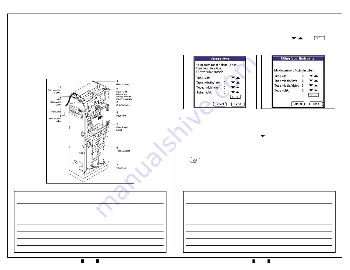
Coin Tube/Cassette
—
available in different denomination configurations
•
Payout Module
—
motor rotation determines which tube pays out coins
A-66 C
HASSIS
C
OMPONENTS
•
MDB Harness
—
provides a 6-pin Connector for MDB communication, and
a 4-pin connector for RC-10 communication
•
Interface Board
—
circuit interface for MDB, Validator Unit, Tube Sensors,
Pay-out Section
•
Cash Box Channel
—
built-in protection against “stringed coins”.
Figure 3
A-66 Features
P
ALM
A66US (C
ONTINUED
)
8. Back on the
‘Coin Settings’
Screen, select
‘Filling Level Limitation’
. The
screen depicted in Figure 24 will appear. Set the desired filling level for each
coin tube by using the respective up and down arrows
. The
Box
allows filling level values to be incremented by one (1) or ten (10) units at a
time.
9. On the
’Coin Settings’
Screen, select
‘Security Stock’
. The screen depicted in
Figure 25 on page 22 will appear. The security stock level for each coin tube can
be set via its respective
'down arrow'
. Each
'down arrow'
allows for a setting
from zero (0) to nine (9). Once the desired level is set, click on the
‘Send’
Screen Button to program the Coin Changer. Clicking
‘Cancel’
will return the
selection back to the
’Coin Settings’
Menu.
10.Back on the
’Coin Settings’
Screen, select
‘Coin Sorting’
. A screen similar to
the one shown in Figure 26 will appear. This screen represents the current coin
tube sorting configuration in use by the Coin Changer. The particular example
shown indicates a tube configuration of
'nickel, dime, quarter, quarter'
,
although the configuration for your unit may be different.
Figure 24
Filling Level Limitation
Screen
Figure 23
Float Level Screen
NOTE: A Security Stock level of three (3) coins is recommended to prevent "coin
bounce" and possible stacking issues in the Coin Changer tubes.


