2-
16
Section 2
Installa
tion
S
tandard Inter
face Cir
cuit Schematics (Continued
3)
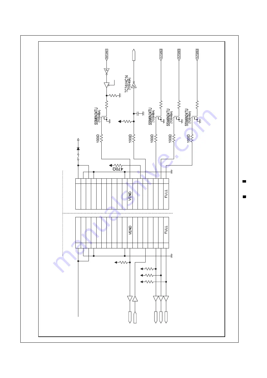
Figure 2-14 illustrates the DBV
-400 ID
-002
Pulse Interface Schematic Diagram.
F
ig
u
re 2-
14
F
ig
u
re 2-
14
DBV
-40
0 ID-
002
Pu
lse In
te
rface Sche
matic
Diag
ra
m
1
2
3
4
5
6
7
8
9
10
11
12
13
14
15
16
17
18
IN12V-24V
GND
IN12V-24V
GND
GND
D/E
BUSY
ABN
IN12V-24V
GND
IN12V-24V
GND
GND
D/E
BUSY
ABN
1
2
3
4
5
6
7
8
9
10
11
12
13
14
15
16
17
18
Power
Power
INLINE1
5V
10k
100P
5V
Sleep Control
C
O
NTROLLER
SID
E
DBV
-40
0 SIDE


