Maintenance
Setting the spindle to zero
1) Fully retract the cylinder. This will bind the spindle and lock the spindle in place. To free up the spindle,
advance the cylinder slightly until the spindle can rotate freely. Rotate the spindle to its normal starting
position. This is where the drive pawl will engage the largest tooth on the drive hub.
2) Rotate the spindle clockwise 45
o
so that the 2 left side dowel pins are lined up with the benders frame. The
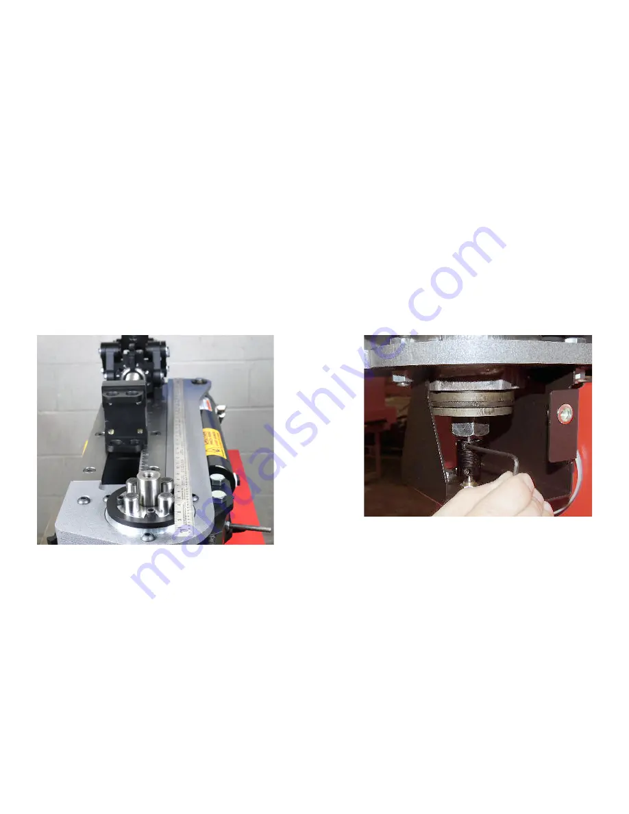
drive paw will now be in position to drive the 2nd tooth. As shown below, using a ruler, place it on the 2 dowel
pins closest to the cylinder. Rotate the spindle until the ruler is as straight as possible with the bender’s frame.
It does NOT have to be perfect. You may need to disengage the drive pawl if you can’t rotate the spindle back
far enough to line up the ruler.
3) Turn the computer off and then back on.
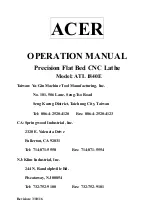
4) As shown below, loosen the encoder coupling’s UPPER set screw.
5) Being sure not to let the spindle move, rotate the encoder until the display reads ‘45.0’. Tighten the set screw.
6) The spindle has now been zeroed. You can verify this by disengaging the drive paw lever and rotating the
spindle counter-clockwise 45
o
so that the display reads ‘0’. The drive largest tooth can now be engaged with
the drive pawl.
Using a ruler to set the spindle readout to 45o
Adjusting the encoder’s coupling.
Page 14


