background image

Chapter 2

Safety information

Laser Safety instructions

User Manual

790000002/00

11

ment are dependent on the cleanliness of the environment and the 
optical connectors as well as the care taken in its manipulation.

The optical connectors must therefore be clean and dust-free. If the 
optical connection is not being used, protect the connections of 
2000 Platform using the protective caps.

Laser Safety instructions

The provisions contained in two standards define the safety procedures 
to be observed both by users and by manufacturers when utilizing laser 
products:

EN 60825-1: 2001 - Safety of laser products – Part 1: Classification 
of products, requirements and user guidelines. 

FDA 21 CFR § 1040.10 - Performance standards for light-emitting 
products - Laser products.

Due to the range of possible wavelengths, power values and injection 
characteristics of a laser beam, the risks inherent in its usage vary. The 
laser classes form groups representing different safety thresholds.

Laser classes

Standards EN 60825-1, Edition 1.2, 2001-08 and FDA21CFR§1040.10: 

VFL option: Class 2.

Warning labels

for the laser

classes

Due to the reduced dimensions of the optical modules, it is not possible 
to attach the required warning labels to them. In line with the provisions 
of Article 5.1 of the EN 60825-1 standard, the laser class identification 
labels are shown below:

The user must take the necessary precautions concerning the optical 
output of the instrument and follow the manufacturer’s instructions.

Reference 
standard

EN 60825-1, Edition 1.2, 2001-08

FDA21CFR§1040.10

Class 1

Class 2

CLASS 1

LASER PRODUCT

LASER RADIATION

DO NOT STARE INTO BEAM

CLASS 2 LASER PRODUCT

LASER RADIATION - DO 
NOT STARE INTO BEAM


CLASS II LASER PRODUCT

CAUTION

Measurements on optical fibers are difficult to execute and the 
precision of the results obtained depends largely on the 
precautions taken by the user.

2000 Platform English rev00.book  Page 11  Lundi, 20. juin 2011  1:47 13

Summary of Contents for 2000 Platform

Page 1: ...alia Enabling Australia s Field Technicians to build troubleshoot and maintain better communications networks Industry Best Pricing Finance Available Short to Medium Project Based Rental Solutions Ded...

Page 2: ...JDSU 2000 Platform Handheld modular Platform designed for the construction turn up and maintenance of fiber networks User Manual 2000 Platform English rev00 book Page i Lundi 20 juin 2011 1 47 13...

Page 3: ...2000 Platform English rev00 book Page ii Lundi 20 juin 2011 1 47 13...

Page 4: ...JDSU 2000 Platform Handheld modular Platform designed for the construction turn up and maintenance of FTTx networks User Manual 2000 Platform English rev00 book Page iii Lundi 20 juin 2011 1 47 13...

Page 5: ...2000 Platform English rev00 book Page iv Lundi 20 juin 2011 1 47 13...

Page 6: ...ountries Netscape Navigator is a trademark or registered trademark of Netscape Communications Corporation in the United States and other countries Specifications terms and conditions are subject to ch...

Page 7: ...on the equipment then the owner should return the equipment directly to the reseller Instructions for returning waste equipment to JDSU can be found in the Environmental section of JDSU s web site at...

Page 8: ...1 Unpacking the instrument 2 About the 2000 Platform 2 Main features 3 Hard keys and Indicators 5 Front panel hard keys 5 Front panel indicators 6 Power Supply 7 Chapter 2 Safety information 9 Batter...

Page 9: ...2000 Platform 18 Resetting the 2000 Platform 18 First start configuring your regional settings 18 Chapter 4 Configuring the 2000 Platform 21 Displaying the System Settings screen 22 Defining the scree...

Page 10: ...Function 33 Talkset configuration 33 Connections 33 Establishing communication 33 Adjusting volume level 34 Disconnection 34 Chapter 6 Scope 35 Scope feature 36 Overview 36 Installation of tips 36 Co...

Page 11: ...Opening files 49 File Types 49 Sorting files 50 Transferring files to a PC 50 Establishing connection 2000 Platform PC 50 Transferring files onto the PC 52 Cancellng the connection 52 Sending files b...

Page 12: ...66 Virtual control buttons bar 67 Equivalence between the keyboard and 2000 Platform 67 Chapter 9 Technical specifications 69 Display specifications 70 Screen 70 Memory 70 Input Output 70 Power supply...

Page 13: ...age 82 Services Data page 82 Accessing to the 2000 Platform documentation 83 Installing a new version of the software 84 Downloading from Internet 84 Installation from a USB memory stick 84 Installati...

Page 14: ...le of Contents User Manual 790000002 00 xiii General information on warranty 97 Hardware Warranty 97 Warranty disclaimer 98 Index 99 2000 Platform English rev00 book Page xiii Lundi 20 juin 2011 1 47...

Page 15: ...Table of Contents xiv User Manual 790000002 00 2000 Platform English rev00 book Page xiv Lundi 20 juin 2011 1 47 13...

Page 16: ...m designed for the construction turn up and maintenance of fiber networks The topics discussed in this chapter are as follows Purpose and scope on page xvi Assumptions on page xvi Technical assistance...

Page 17: ...iently We are assuming that you have basic computer and mouse track ball experience and are familiar with basic telecommunication concepts and terminology Technical assistance If you need assistance o...

Page 18: ...scription Example User interface actions appear in this typeface On the Status bar click Start Buttons or switches that you press on a unit appear in this TYPEFACE Press the ON switch Code and output...

Page 19: ...s symbol represents a risk of electrical shock NOTE This symbol represents a Note indicating related information or tip This symbol located on the equipment or its packaging indicates that the equipme...

Page 20: ...ption of the 2000 Platform Topics discussed in this chapter include the following Unpacking the instrument on page 2 About the 2000 Platform on page 2 Main features on page 3 Hard keys and Indicators...

Page 21: ...in the field and different kinds of module are usable OTDR Modules PON Selective Power Meter OLP CWDM Analyzer Modules C OSA The 2000 Platform employs multi tasking for the simultaneous perfor mance o...

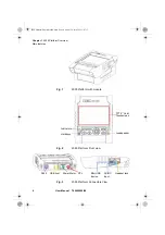
Page 22: ...a headset A connection socket for the mains adapter providing the 12 V power supply and used to charge the battery LED indicators for Charge On status and Test A Li Polymer battery A module interchang...

Page 23: ...0 Platform with module Fig 2 2000 Platform Front view Fig 3 2000 Platform Connectors View Hardkeys Indicators Loudspeaker TFT 5 Color Touchscreen RJ45 USB host Power Meter VFL Mini USB device AC DC In...

Page 24: ...iles with facilities for classifying them in direc tories and sub directories Gives access to selection of the different measurement or functions the settings of the instrument the help page This butt...

Page 25: ...y are used to scroll through the menus the central button serving to select or confirm the parameter chosen Table 3 Indicators Status On indicator Blicking green The instrument though connected to an...

Page 26: ...ry an AC adapter charger via a power cable on which has been set the correct country adaptable plug Fig 5 Delivered elements for 2000 Platform supplying Interchangeable plugs Power supply plug UK adap...

Page 27: ...Chapter 1 2000 Platform Overview Power Supply 8 User Manual 790000002 00 2000 Platform English rev00 book Page 8 Lundi 20 juin 2011 1 47 13...

Page 28: ...e main information on the safety conditions when using the 2000 Platform Battery and AC DC safety information on page 10 Precautions relating to optical connections on page 10 Laser Safety instruction...

Page 29: ...c safety precautions are as follows Do not use AC Adapter Charger outdoors or in wet or damp loca tions Connect the AC Adapter Charger to the correct mains voltage as indicated on the ratings label Do...

Page 30: ...inherent in its usage vary The laser classes form groups representing different safety thresholds Laser classes Standards EN 60825 1 Edition 1 2 2001 08 and FDA21CFR 1040 10 VFL option Class 2 Warnin...

Page 31: ...Chapter 2 Safety information Laser Safety instructions 12 User Manual 790000002 00 2000 Platform English rev00 book Page 12 Lundi 20 juin 2011 1 47 13...

Page 32: ...cussed in this chapter are as follows Fitting and removing a module on page 14 Setting the adaptable plug to the mains adapter on page 15 Charging the battery on page 16 Switching the 2000 Platform on...

Page 33: ...ng the 2 screws 3a fixing the receptacle Removing a module 1 Unscrew the two captive fixing screws of the module completely up to the stop 2 Remove the two slots of the module from their housing onto...

Page 34: ...able plugs Europe UK US Australia Japan To set the correct plug to the mains adapter 1 Make flush the connector onto the mains adapter with the adaptable plug slots 2 Push the adaptable plug until it...

Page 35: ...witched on but not plugged to mains 3 The battery can then be charged and the Platform used simultane ously Charging the battery On connection to the mains if the user does not press ON the battery wi...

Page 36: ...ally after saving the current configuration and measurement Switching the 2000 Platform on and off Switching on the 2000 Platform 1 Press the ON OFF key If the Platform is powered to mains the battery...

Page 37: ...irst screen displayed allows to configure the regional settings Those settings will be kept in memory and automatically applied on the instrument each time it is restarted NOTE It is possible to switc...

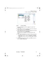
Page 38: ...me using the numeric keypad displayed using the menu key Edit Number The date and time are displayed on the upper right side of the screen 4 Click on Date Time Format and configure the following param...

Page 39: ...Chapter 3 Starting up First start configuring your regional settings 20 User Manual 790000002 00 2000 Platform English rev00 book Page 20 Lundi 20 juin 2011 1 47 13...

Page 40: ...discussed in this chapter are as follows Displaying the System Settings screen on page 22 Defining the screen parameters of the 2000 Platform on page 23 Defining the Audio parameters of the 2000 Platf...

Page 41: ...ettings screen you must 1 Press the HOME hard key to reach the Home page 2 Activate the Settings icon to open the System Settings screen Fig 9 Home page Fig 10 System Settings page NOTE If you are in...

Page 42: ...strument is used Indoor to be selected when the instrument is used inside see Figure 10 on page 22 Outdoor to be selected in order to optimize the readability of the screen for an outside use Screen S...

Page 43: ...the volume on the line Headset Volume using the left and right direction keys or the Numeric keypad displayed with the softkey Edit Number Min volume for Headset function 0 Maxvolume for Headset func...

Page 44: ...rences in Chapter 10 Options and accessories for details The topics discussed in this chapter are as follows Connection to the power meter VFL and Talkset on page 26 Using the Power meter on page 26 V...

Page 45: ...s the HOME button 2 Activate the power meter icon of the Platform The effect of this action will to be to bring the power meter into use and to display the Results page for Power Meter Configuring the...

Page 46: ...nd must be heard when a modulation occurs Yes No Unit Unit of power displayed Watt dBm for displaying absolute power dB for displaying a result relative to a reference link loss Reference level If dB...

Page 47: ...r meter is displayed in large charac ters in the units selected in the SETUP menu together with the mode of transmission of the signal measured continuous CW or modulated to a frequency of 270Hz 330Hz...

Page 48: ...are saved Commands of the power meter parameters When the LTS function is selected the following softkeys are available on the results page Keep Result Saves the result on the corresponding line of t...

Page 49: ...stop the measurement Optical link loss Setting the zero value of the power meter 1 Fix the plug over the optical input of the power meter so that no light can reach the photodiode of the power meter I...

Page 50: ...ix the jumpers and connectors needed to connect the fiber to be tested between the source output and the power meter input 2 In the set up menu select dB units 3 The power displayed in the Power Meter...

Page 51: ...on FILE and select Store trace Two files are being saved The first file is used with the 2000 Platform and allows to retrieve all measurement results It is saved with the extension Lts The second file...

Page 52: ...f the fiber 1 Connect the fiber to the Talkset port of the 2000 Platform either directly or through jumpers 2 A headset with earphones and a microphone supplied with the option may also be plugged int...

Page 53: ...aker and adjust the volume 1 Press the HOME key 2 Validate Settings icon to reach the System Settings page 3 Under the Audio box select Headset Volume and adjust the volume Disconnection When communic...

Page 54: ...ee References of accesso ries page 76 The topics discussed in this chapter are as follows Scope feature page 36 Installation of tips page 36 Configuring the P5000 Scope page 37 Starting up with the sc...

Page 55: ...e P5000 requires an FBPT inspection tip and is connected to the 2000 Platform with a USB 2 0 connector Installation of tips The Pass Fail analysis function on the 2000 Platform can only be used with c...

Page 56: ...e the test The following screen displays Test On the line Profile select the Profile which will be used for the test of fiber connector IEC SM UPC Pass Fail criteria for single mode UPC connectors fro...

Page 57: ...isplay by clicking on the right arrow key to enter a specific name for the fiber On the line Fiber Number use the numeric keypad which will display by clicking on the right arrow key to enter the fibe...

Page 58: ...re displayed on the key You may also choose to use the function Auto Contrast in order to get settings calculated automatically by the instru ment Fig 19 Example of the result using the P5000 scope NO...

Page 59: ...ing a test of the connector and fiber end face Once the Brightness and Contrast parameters are correctly defined for the current image see Luminosity and Contrast settings page 39 a test of fiber conn...

Page 60: ...C represents the Ferrule zone it identifies a portion of the ferrule near and around the fiber NOTE To configure the Pass Fail critera refer to Configuring the Scope on page 37 Fig 20 Test results Te...

Page 61: ...ed Camera All the Contrast and Luminosity settings are available just like in full screen Snapshot The live picture from the camera is frozen but does not replace the live picture at position 1 The ne...

Page 62: ...ode page 42 File menu Saving the test result in a jpg file Once the test has been performed and the result is displayed on the 2000 Platform screen 1 Press FILE key 2 Click on Save key to save a jpg f...

Page 63: ...been generated 1 Return to the HOME page and select the File Explorer 2 Select the pdf file of the report in the directory Scope 3 Press Load Confirm Load NOTE The pdf report will be saved on the disk...

Page 64: ...apter are as follows File Explorer Overview on page 46 Directories and Files selections on page 46 Directories Files editing functions on page 47 Working with directories and files from the explorer o...

Page 65: ...ge 1 Press on the directory that must be selected on the left of the screen The list of files the directory countains displays on the right side of the screen The selected directory is underlined in b...

Page 66: ...are selected or Click on Select all menu key to select all files into the directory Directories Files editing functions Copy Cut Paste files directories To copy cut one or several files or one direct...

Page 67: ...he entire name 4 Enter a new name for the directory file 5 Click on Enter to validate the new name Deleting a directory file 1 Select the directory or file s to be deleted see Directories and Files se...

Page 68: ...orm the types are symbolized by icons E g Opening several files at the same time can be done exclusively with trace files example all OTDR trace files if a reference trace has been defined Other type...

Page 69: ...opposite order Sort by date clicking once on this key the 2000 Platform displays files from the more recent to the less one By clicking again on key the Platform displays files from the older to the m...

Page 70: ...ttom right side of the PC informing a new hardware is detected 3 Click on the message and select Open folder to view files in the dialog box JDSUDISK F F is an example it can be different according to...

Page 71: ...e s will be transferred 4 Press Ctrl V or right click and select Paste Cancellng the connection Once all desired files have been transfer onto the PC connection between 2000 Platform and PC can be rem...

Page 72: ...creen appears 4 Do one of the following Press the Become Pairable soft key to wait for another device to initiate the connection to the 2000 or If the desired device is not displayed on the screen or...

Page 73: ...The icon has a blue background when paired with a device You can now go to the file explorer and transfer files from the 2000 Plat form toward the bluetooth device and vice versa Transfering files vi...

Page 74: ...captures of what is displayed on the screen directly from the 2000 Platform Configuring the parameters of screenshots To configure the screenshot and choose the format of the generated file 1 Press H...

Page 75: ...the screenshots files The screenshot is saved in a file which is automatically named as follow Print_date year month day _time hour minut second jpg png pdf The file is saved in the directory Print o...

Page 76: ...saved in a report in JPG PNG or PDF format 2 If necessary make the modifications on the file trace see user manual of the 2100 OTDR Modules for OTDR trace files 3 Set the trace view as wished For OTD...

Page 77: ...report file the name of the JPG PNG PDF file is as follow name of the stored trace_date year month day _time hour minute second jpg png pdf Merging pdf or txt files In the Explorer page two pdf files...

Page 78: ...tically saved in the same directory as the one where files have been selected It gathers all results from pdf txt files selected and traces for pdf file in one single pdf file of several pages 1 resul...

Page 79: ...mory stick always select a storage device different from usbflash select disk for example in the explorer 2 Make sure you no longer have any running applications using the usbflash storage media 3 The...

Page 80: ...ns for storage media The abbreviations used in the explorer for the different storage media are Abbreviation Storage medium disk Internal flash memory usbflash USB memory stick bluetooth inbox Bluetoo...

Page 81: ...Chapter 7 File management Storage media 62 User Manual 790000002 00 2000 Platform English rev00 book Page 62 Lundi 20 juin 2011 1 47 13...

Page 82: ...ace onto a PC or to access the internal memory or USB memory stick contents on the PC Topics described in this chapter are as follows Establishing connection on page 64 Transferring the Interface on p...

Page 83: ...atform validate the Settings icon 2 In the System Settings page in the I O Interfaces box configure the following parameters Ethernet Mode Parameters of the local Ethernet network to which the 2000 Pl...

Page 84: ...n the 2000 Platform tries to establish a connection to obtain an address from a DHCP server If for any reason this process fails the 2000 Platform reverses to static IP address mode with User1 IP addr...

Page 85: ...0 33 18 93 5800 3 Press Enter to validate A VNC window opens demanding a password 4 Press OK without typing any password The screen of the 2000 Platform appears offset on your PC You can use keyboard...

Page 86: ...keys on the front panel of the 2000 Platform Equivalence between the keyboard and 2000 Platform The PC keyboard can replaced all the buttons and keys of the 2000 Plat form except the ON OFF button The...

Page 87: ...scape Echap a The Export function is available directly on the 2000 Platform pushing simultaneously the left and right arrow keys Function on the 2000 Platform Externalkeyboard NOTE Those equivalences...

Page 88: ...atform mainframe The topics discussed in this chapter are as follows Display specifications on page 70 Memory on page 70 Input Output on page 70 Power supply on page 70 Dimensions Weight on page 71 En...

Page 89: ...are available for data storage Input Output two USB 2 0 host ports one Mini USB 2 0 device one RJ 45 connector for Ethernet interface 10 100 1G built in loudspeaker headset jack Power supply Battery T...

Page 90: ...n backlight with an OTDR QUAD Module with an OTDR LM Module Up to 3h Up to 3h45 Standard Mains Adapter Input 100 250 V 50 60 Hz Output 12V DC 2 5 A max Compliance EN 60950 Weight 2000 Platform without...

Page 91: ...nwood floor of 5 cm thickness 1 impact on each of its 6 sides with power off Shocks The 2000 Platform resists the following test 3 shocks per axis along each of the 3 axes with power off Impacts of 15...

Page 92: ...haracteristics of the options Power meter option Specifications given for 25 C after 20 minutes stabilization time and after zero setting Wavelength range 800 to 1650 nm in steps of 1 nm Calibrated wa...

Page 93: ...Chapter 9 Technical specifications Characteristics of the options 74 User Manual 790000002 00 2000 Platform English rev00 book Page 74 Lundi 20 juin 2011 1 47 13...

Page 94: ...sories of the 2000 Platform The topics discussed in this chapter are as follows References of options for the 2000 Platform on page 76 References of accessories on page 76 References of manuals on pag...

Page 95: ...tform E20PM Power Meter and VFL option for T BERD MTS 2000 Platform E20PMVFL Power Meter and Talkset option for T BERD MTS 2000 Platform E20TSPM Mains options Reference Cigarette lighter adapter for 2...

Page 96: ...tform Modules are available in pdf format into the unit The printed versions of the manuals are available on option in French English and German 3 Free software updates on the Web but without user man...

Page 97: ...Chapter 10 Options and accessories References of result processing software 78 User Manual 790000002 00 2000 Platform English rev00 book Page 78 Lundi 20 juin 2011 1 47 13...

Page 98: ...t and identify and correct problems related to the 2000 Platform The topics discussed in this chapter are as follows Maintenance procedure on page 80 Recycling Information on page 92 Troubleshooting o...

Page 99: ...the high quality of the instrument continue to be ensured after repair work This procedure also has the advantage of reducing repair costs and time In the interests of quality and efficiency we strong...

Page 100: ...an extension Accessing to the 2000 Platform information On the 2000 Platform some screens allows to display information on different elements of the equipment To display the information on the 2000 Pl...

Page 101: ...s to visualize the software options available on the 2000 Platform 1 Once on the About screen press Software Options menu key to display the list of software options available on your 2000 Platform Se...

Page 102: ...available onto the equipment To display the list of documents available for 2000 Platform use 1 Validate the Help icon on the Home page 2 Click on Link to PDF User Manual 3 In the new page click one...

Page 103: ...layed click on Save to save the exe file on the PC 7 Once completed connect the USB memory stick to the PC and follow the instructions chapter Installation from a USB memory stick on page 84 from step...

Page 104: ...net on page 84 b Once the transfer is completed double click on the exe file A window will appear Check that the folder is correct i e the USB memory stick driver is appearing in the line at the botto...

Page 105: ...rom Ethernet Before starting the software upgrade via Ethernet make sure the IP adress of the PC server The update can be performed directly onto the equipment using an http address 1 Connect the 2000...

Page 106: ...pgrade of the selected software s or Click on Confirm All Choices to upgrade all versions Upgrading begins The 2000 Platform is automatically rebooted Upgrading takes several minutes At the end the 20...

Page 107: ...m USB After a few seconds a new page displays indicating that to continue the reboot the validation key must be pressed Press the hard key The reboot starts automatically Once the upgrade is completed...

Page 108: ...tions will be installed At the end of this sequence you will be asked to reboot the unit to apply the modifications pushing the key Confirm the reboot to restart the Platform Import the license from t...

Page 109: ...ically and your software options will be installed 6 At the end of this sequence you will be asked to reboot the unit to apply the modifications pushing the key 7 Confirm the reboot Locking the 2000 P...

Page 110: ...ing the text edition Unlocking the 2000 Platform 1 Once the locking screen is displayed click on the key Unlock Instrument 2 Press confirm to confirm the Platform must be unlocked 3 Enter the password...

Page 111: ...ce Centers the cost of a replacement sub assembly will be invoiced Recycling Information JDSU recommends that customers dispose of their instruments and peripherals in an environnmentally sound manner...

Page 112: ...e touchscreen needs to be calibrate See Touchscreen calibration on page 94 Error message when USB has been disconencted The USB disconnection has not been done prop erly see USB memory stick disconnec...

Page 113: ...ystem Settings page 2 Press Expert Tools Media Utilities 3 Select Erase Disk to delete all the disk contents into the 2000 Plat form A confirmation must be validated before the deletion Touchscreen ca...

Page 114: ...cess the battery of the 2000 Platform proceed as follows 1 Switch off the instrument and disconnect the mains supply 2 Turn the instrument face down on the work surface 3 If any remove the module inst...

Page 115: ...o the Platform 2 Connect the new battery in the connector of the 2000 Platform in the right way using the location notch Fig 54 Battery installation Battery door Battery Date and Time parameters will...

Page 116: ...rdered the warranty period shall begin upon shipment to Customer Hereafter these periods of time shall be collectively referred to as the Initial Warranty Period JDSU s obligation and customer s sole...

Page 117: ...software shipped to JDSU for repair or replace ment JDSU shall pay all transportation costs associated with returning repaired or replaced product to customer Warranty disclaimer For hardware and or...

Page 118: ...etooth pairing 53 search devices 53 specifications 73 C Cleaning optical connectors 10 plates housings and screen 80 Connectors cleaning 81 CSV file 49 E Environment 72 F File sending by bluetooth 54...

Page 119: ...connection 26 file management 32 measurement 31 reference 76 reference measurement 31 results 28 specifications 73 zero value 30 Power Meter file 49 Processing software reference 77 R Report 56 result...

Page 120: ...the instrument 2 USB connection 60 disconnection 60 upgrade via 84 User manual reference 77 V VFL connection 26 emission of light 32 function 31 specifications 73 X XML file 50 2000 Platform English...

Page 121: ...Index User Manual 790000002 00 102 2000 Platform English rev00 book Page 102 Lundi 20 juin 2011 1 47 13...

Page 122: ...2000 Platform English rev00 book Page 103 Lundi 20 juin 2011 1 47 13...

Page 123: ...99 Fax 1 240 404 2195 Latin America Tel 55 11 5503 3800 Fax 55 11 5505 1598 Asia Pacific Tel 852 2892 0990 Fax 852 2892 0770 EMEA Tel 49 7121 86 2222 Fax 49 7121 86 1222 www jdsu com E2000M02 UM 06 11...

Reviews: