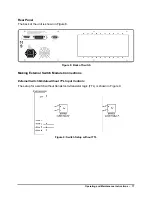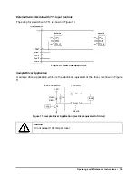
Powering Up the Unit
To power up the unit:
1. Connect the unit to the AC power source, with the AC power cord provided.
2. Set the power switch to
I
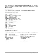
(on). All key lamps and status LEDs light during the power-up
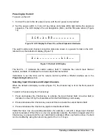
sequence. The LCD displays the unit designation (SCG) and the firmware version (Figure
12).
Figure 12: LCD Display for Power On, without Expansion Hardware
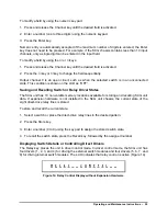
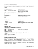
The switch number and channel connection status are shown in a generic format on the LCD,
referred to as the default unit display (Figure 13).
Figure 13: Default LCD Display
The field “S : 1” indicates the switch number, field “1” indicates the current input channel
number, and field “2” indicates the current output channel number.
Instructions to set the SCG unit for remote control by GPIB or RS232 interface are in the
Selecting Input Channels and Output Channels
When the default unit display is active (Figure 13), the Channel key is lit on the front panel of
the unit.
To select a channel using the Channel key:
1. Press and release the Channel key to activate the input channel field. An active field is
indicated on the LCD by the characters within that field blinking continuously.
2. Press and release the Channel key a second time to activate the output channel field.
3. Press and release the Channel key again to deactivate all fields.
Fields that have only one possible parameter (for example, a unit with a single input channel)
cannot be selected. When there is only one parameter selection, the field is skipped when the
Channel key is pressed and the next valid field is activated. When any field is active, the field
can be modified by using the numeric key pad or the
▲
or
▼
keys.
Operating and Maintenance Instructions –
19

