18 Installation and Physical Interface
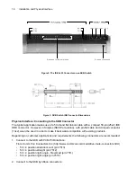
Figure 4: Additional Dimensions
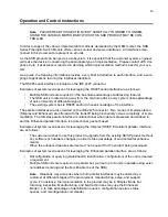
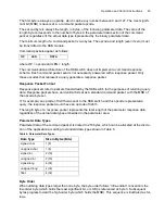
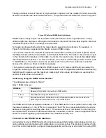
Operating and Maintenance Instructions
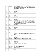
Pinout Information for the Switch
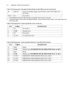
The signals for communication are connected via the 50-pin (25x2 IDE) connector. Power inputs are
connected either through the 4 pin power pins on the 4x1 portion of the IDE connector, or using the
power pins located on the IDE 25x2 communications connector.
Summary of Contents for SKB Series
Page 1: ...SKB SERIES FIBEROPTIC SWITCH MODULE User Manual ...
Page 2: ...ii 10109002 Rev 001 August 2001 2001 JDS Uniphase All rights reserved ...
Page 4: ...iv ...
Page 11: ...7 Contents ...
Page 13: ...9 List of Figures ...
Page 15: ...11 List of Tables ...
Page 19: ...4 Safety Information Instructions and Symbols ...
Page 25: ...10 Introduction ...
Page 53: ...38 Operation and Control Instructions ...
Page 91: ...76 Commands ...
Page 111: ...96 Application Notes ...
Page 113: ...98 Service ...


