26 Operation and Control Instructions
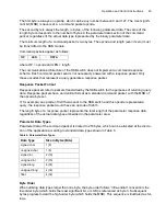
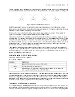
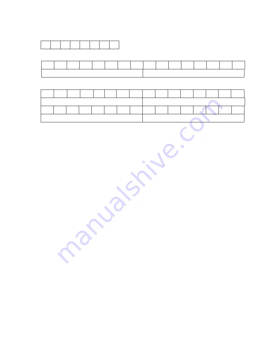
Single-byte bit order:
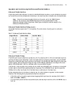
Double-byte bit order:
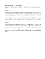
Quadruple-byte bit order:
Example:
The 16-bit number represented by 0x1234h is split into two bytes as follows: 0x34h (Byte 0) and
0x12h (Byte 1). In the command or response packet, however, these bytes are contiguous and there-
fore appear as 0x3412h.
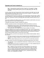
Operation and Control using the RS485 Serial Interface
The RS485 interface is a two wire differential bus used to communicate serially with the master
device. The SKB RS485 interface operates over a range of 2400 to 4800 baud. The default baud
rate for the switch is 2400 baud asynchronous, self-clocking.
The RS485 communication settings are:
•
Eight data bits
•
One stop bit
•
No parity bits
•
2400 (default) and 4800 baud rate
Simultaneous operation of serial and parallel interface is not supported.
Connecting Multiple Switches using the RS485 Interface
Up to 31 RS485 unit loads can be connected to the differential bus. Therefore up to 30 SKB
switches and one master controller can be used to construct an RS485 network. Exceeding the limit
of 31 devices excessively loads the RS485 drivers and attenuates the differential signal. The conse-
quence is reduced noise immunity of the bus and an increased error rate. Operation of more than 30
SKB’s with a single master is not recommended nor guaranteed.
The most appropriate method of connecting RS485 nodes is by multidropping the connection from
master to node 1, to node 2, and onward to node n. The bus must form a single continuous path.
Bit
7
6
5
4
3
2
1
0
Bit
15
14
13
12
11
10
9
8
7
6
5
4
3
2
1
0
Byte 0 (low)
Byte 1 (high)
Bit
31
30
29
28
27
26
25
24
23
22
21
20
19
18
17
16
Byte 0 (low)
Byte 1
Bit
15
14
13
12
11
10
9
8
7
6
5
4
3
2
1
0
Byte 2
Byte 3 (high)
Summary of Contents for SKB Series
Page 1: ...SKB SERIES FIBEROPTIC SWITCH MODULE User Manual ...
Page 2: ...ii 10109002 Rev 001 August 2001 2001 JDS Uniphase All rights reserved ...
Page 4: ...iv ...
Page 11: ...7 Contents ...
Page 13: ...9 List of Figures ...
Page 15: ...11 List of Tables ...
Page 19: ...4 Safety Information Instructions and Symbols ...
Page 25: ...10 Introduction ...
Page 53: ...38 Operation and Control Instructions ...
Page 91: ...76 Commands ...
Page 111: ...96 Application Notes ...
Page 113: ...98 Service ...

