34 Operation and Control Instructions
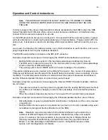
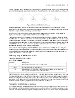
The following general rules apply:
•
The master needs to ensure that the BUSY line is de-asserted (low) before toggling any parallel
communication lines (for example, /SOP, /STROBE, and so on).
•
Communication lines must be toggled according to the steps indicated in the protocol flow charts
for read and write operations. Poll the error line following each operation.
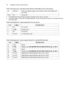
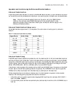
Enhanced Parallel Interface Line Descriptions
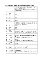
Data Lines (D0...D7)
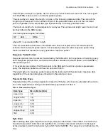
Byte data is composed of a binary eight-bit pattern presented on the /D0 to /D7 data lines. Input and
output byte data are presented the same way.
The value 0 indicates that the input needs to be set low (for example, <0.8 V DC).
The value 1 indicates that the input needs to be set high (for example,
>
2 V DC).
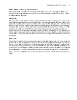
/SOP Input Line
The /SOP line provides a data packet start/stop mechanism. Transition of the /SOP line from a high-
to-low state indicates the beginning of a data packet, and all subsequent bytes placed on the data
lines are considered packet data bytes. Transition of the /SOP line back from a low-to-high state indi-
cates the end of a data packet. The busy signal MUST drop before the /SOP command is with-
drawn, or the communication sequence will be aborted. The master is responsible for controlling
the /SOP line.
/STROBE Input Line
The /STROBE line is used to signal the SKB switch to read data from or write data to the data lines.
A change on the data lines has no effect until there is a high-to-low transition on the /STROBE line.
The /STROBE line is driven by the master for both transmit and receive operations.
R/W Input Line
The R/W line is driven by the master as a bus control mechanism. When the R/W line is driven low, /
D0-/D7, /SOP, and /STROBE line transitions are interpreted as input operations from the master to
the slave. When R/W is driven high, operations are interpreted as output from the slave to the mas-
ter.
BUSY Output Line
The BUSY line provides a flow control mechanism. The BUSY line is pulled high by the slave after
each byte is transferred. The master does not toggle any lines until a high-to-low transition of the
BUSY line is detected.
ERROR Output Line
The ERROR line is used to flag the master when the slave detects an error. When the error line is
high, there is an error in the error queue. The ERROR line is driven low when the errors are read out
of the error queue or the error queue is cleared.
/RESET
Reset resets the micro-controller unit (MCU) in the switch. All communication interfaces are reset.
Summary of Contents for SKB Series
Page 1: ...SKB SERIES FIBEROPTIC SWITCH MODULE User Manual ...
Page 2: ...ii 10109002 Rev 001 August 2001 2001 JDS Uniphase All rights reserved ...
Page 4: ...iv ...
Page 11: ...7 Contents ...
Page 13: ...9 List of Figures ...
Page 15: ...11 List of Tables ...
Page 19: ...4 Safety Information Instructions and Symbols ...
Page 25: ...10 Introduction ...
Page 53: ...38 Operation and Control Instructions ...
Page 91: ...76 Commands ...
Page 111: ...96 Application Notes ...
Page 113: ...98 Service ...


