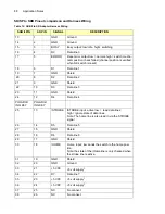
1. Construct a cable wired as outlined inTable 13.
1. Invert the signals on these lines.
2. Connect these lines with the shield lines wrapped around the signal lines.
3. Connect the cable between the printer port and the parallel interface connector of the SKB
switch.
4. Connect a 5 V power source to the power connector of the SKB switch
5. IMPoConnect a ground wire between the PC chassis and the power source ground.
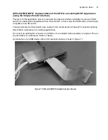
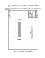
APPLICATION NOTE: Custom SKB with D Subminiature Style connectors
A variant of the SKB has been developed that has a more ruggedized connector interface. That vari-
ant is described in this application note.
All control information contained in the body of this manual applies to this variant. Hence, this appli-
cation note addresses physical features only.
Table 13: Cable Wiring for Printer Port LPT2 Use
Printer Signal
Name
Register
Bit
(Hex
Address)
Number
PC Connector Pin
SKB Pin
SKB Signal
Name
Line Feed
(37A) 1
1
14
20
/STROBE
Data 0
(378) 0
2
14
D0
Data 1
(378) 1
3
2
D1
Data 2
(378) 2
4
3
D2
Data 3
(378) 3
5
16
D3
Data 4
(378) 4
6
17
D4
Data 5
(378) 5
7
5
D5
Data 6
(378) 6
8
6
D6
Data 7
(378) 7
9
19
D7
PE
(379) 5
12
8
BUSY
STROBE
(37A) 0
1
1
12
R/W
SLCT
(379) 4
13
9
ERROR
SLIN
(37A) 3
1
17
22
/HOME
INIT
(37A) 2
1
16
11
/SOP
Printer Port
Ground
2
18, 19, 20, 21, 22,
23, 24, 25
1, 4, 7, 10, 13,
15, 18, 21, 24
Shield
2
Power Source
Ground
Power Ground
Summary of Contents for SKB Series
Page 1: ...SKB SERIES FIBEROPTIC SWITCH MODULE User Manual ...
Page 2: ...ii 10109002 Rev 001 August 2001 2001 JDS Uniphase All rights reserved ...
Page 4: ...iv ...
Page 11: ...7 Contents ...
Page 13: ...9 List of Figures ...
Page 15: ...11 List of Tables ...
Page 19: ...4 Safety Information Instructions and Symbols ...
Page 25: ...10 Introduction ...
Page 53: ...38 Operation and Control Instructions ...
Page 91: ...76 Commands ...
Page 111: ...96 Application Notes ...
Page 113: ...98 Service ...


