15
Installation and Physical Interface
Overview of Physical Interfaces
In order to support the various implementations demanded by the OEM market, the SKB Series
Fiberoptic Switch Module offers various control and power interfaces/ protocols. All interfaces/ pro-
tocols documented in this manual are present on the SKB connector.
Example of typical applications and methods of implementation are provided (for the power and
communication interfaces) in the section on Operation and Control.
Physical Interface
Physical Interface: The SKB Connector
A 50 pin male connector services both parallel and serial communication interfaces (JDS part num-
ber S010604).
The connector on the SKB switch is an IDE, 50(2x25) male + 4 male power, PCB, edge-mount con-
nector, (Comm Con P/N 7514).The recommended mate for SKB operation is an IDE, 50(2x25)
4 female power, right angle connector (Comm Con P/N 7510).The recommended mate for
SK emulation is a 2x13 female ribbon connector.
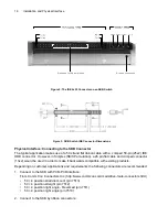
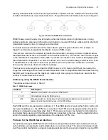
For details on pin numbering and connector dimensions, please refer to Figure 2 and Figure 3
respectively. For further information about connector specifications, please contact:
Comm Con Connectors, Inc.
1848 Evergreen Street, Duarte, CA 91010
Phone: (626) 301-4200 Fax: (626) 301-4212
Email: i
nfo@commcon.com
Home Page:
http://www.commcon.com
Summary of Contents for SKB Series
Page 1: ...SKB SERIES FIBEROPTIC SWITCH MODULE User Manual ...
Page 2: ...ii 10109002 Rev 001 August 2001 2001 JDS Uniphase All rights reserved ...
Page 4: ...iv ...
Page 11: ...7 Contents ...
Page 13: ...9 List of Figures ...
Page 15: ...11 List of Tables ...
Page 19: ...4 Safety Information Instructions and Symbols ...
Page 25: ...10 Introduction ...
Page 53: ...38 Operation and Control Instructions ...
Page 91: ...76 Commands ...
Page 111: ...96 Application Notes ...
Page 113: ...98 Service ...

