Operation and Control Instructions 33
Operation and Control using the Enhanced Parallel Interface
Enhanced Parallel Interface
The Enhanced Parallel interface is similar to the RS485 Serial interface, as all instructions received
by the switch are command packets containing a command opcode, a length code, and parameters.
Note:
Since the command packet structure is the same as for the RS485 Serial
Interface, the sections under RS485 that deal with Command Packet Format,
Response Packet Format, Parameter Data Types, and Byte Order also apply to the
Enhanced Parallel Interface
Enhanced Parallel Interface Voltage Levels
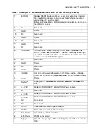
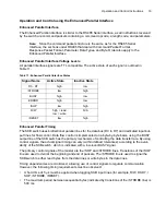
All parallel interface signals are TTL compatible. The active state of each signal is outlined in
Table 11.
Enhanced Parallel Timing
The SKB switch uses bidirectional parallel lines for the data bus (D0 to D7) and dedicated input/out-
put lines for flow control. Data flow control is implemented on a byte-by-byte basis, using the BUSY
output line of the SKB switch as the primary mechanism of controlling the data transfer rate. By using
control signals, the actual signal timing can vary (within defined tolerances) according to the avail-
ability of the SKB switch, which is indicated with a low-level BUSY signal.
The primary control signals of the master are the /SOP and /STROBE lines. Transitions of the /SOP
line are used to delimit the beginning and end of packets. The /STROBE line is used to signal the
SKB switch to either read bytes from the data lines or write bytes to the data lines.
Timing dependencies are minimized, allowing use of control signals to regulate communication.
However, the following timing requirements must be observed:
•
A hold time of 5 µs must be applied when toggling SKB input lines (for example, R/W, D0-D7, /
SOP, /STROBE, /RESET).
•
The maximum period between sequential bytes (indicated by transitions of the /STROBE line) is
500 ms.
Table 11: Enhanced Parallel Interface States
Signal Name
Active State
Inactive State
D0 - D7
high
low
/STROBE
low
high
BUSY
high
low
ERROR
high
low
/SOP
low
high
R/W
high = read
low = write
N/A
/RESET
low
high
Summary of Contents for SKB Series
Page 1: ...SKB SERIES FIBEROPTIC SWITCH MODULE User Manual ...
Page 2: ...ii 10109002 Rev 001 August 2001 2001 JDS Uniphase All rights reserved ...
Page 4: ...iv ...
Page 11: ...7 Contents ...
Page 13: ...9 List of Figures ...
Page 15: ...11 List of Tables ...
Page 19: ...4 Safety Information Instructions and Symbols ...
Page 25: ...10 Introduction ...
Page 53: ...38 Operation and Control Instructions ...
Page 91: ...76 Commands ...
Page 111: ...96 Application Notes ...
Page 113: ...98 Service ...


