background image


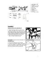
Spurs 


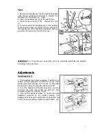
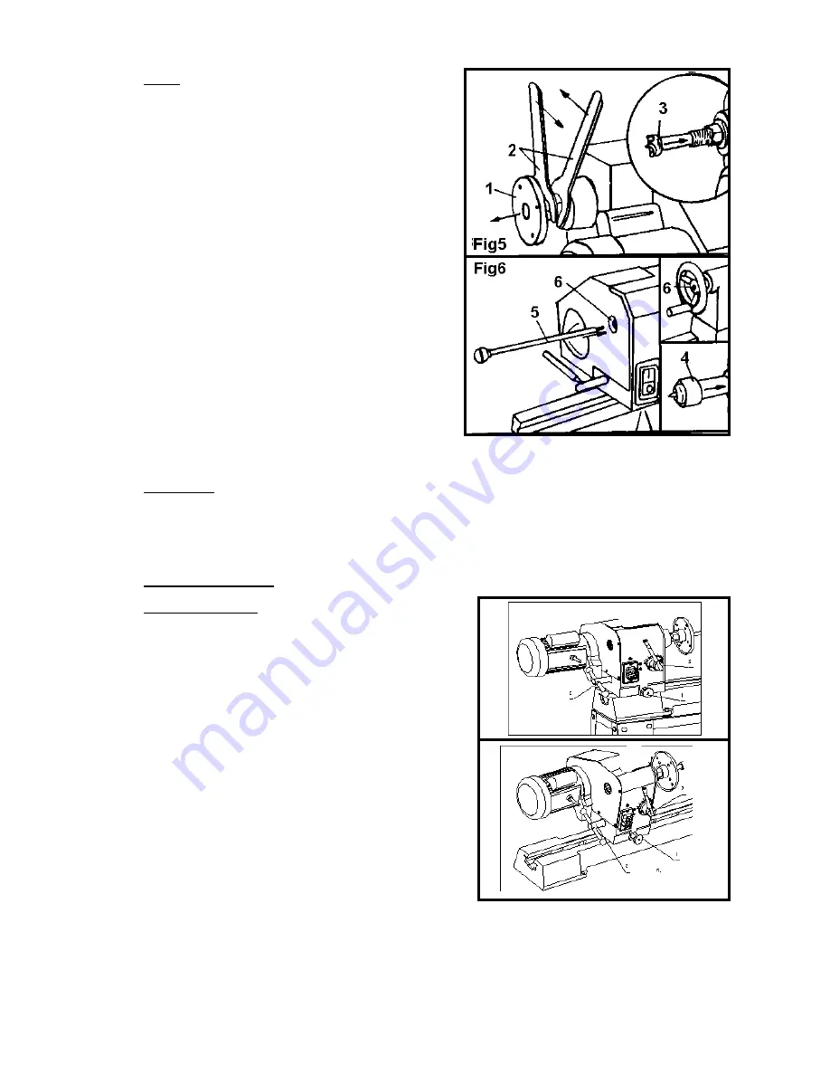
1. Remove the faceplate [1] from the headstock spindle 

using  the  two  wrenches  provided  [2]  to  separate  the 
faceplate from the spindle nut.    (Fig5) 

2. Insert the headstock spur [3] in the spindle hole. 
3. Insert the live center [4] in the      tailstock hole. (Fig 
6) 

4. To remove either the headstock spur or the tailstock 
center insert the push-out rod [5] into the hole [6] at 

the opposite end of the headstock or tailstock. Remove 
and store the rod in a safe location after use. 


WARNING!

  Do  not  operate  your  wood  lathe  until  it  is  completely  assembled  and  adjusted 

according to the instructions. 


Adjustments 

Headstock (Fig 7) 
 

1. The headstock has 5 preset positions, 0

setting for all 

spindle  turning  applications,  60

0

/90

0

/120

0

  for  use  when 

making  face  plate  turnings,  180

0

  for  use  for  face  plate 

turnings when using the extension bed and tool rest. 

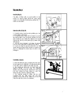
2. To set the headstock at the desired position, you must 
first  turn  the  head  lock  handle  [2]  until  you  have 
completed at least one rotation. (Fig 8) 
3.  Pull  out  the  headstock  release  [1],  rotate  the  entire 
headstock  clockwise  to  the  desired  position.  The 

headstock will be fixed in position when it clocks into one 
of the five pre-set settings. Tighten the lock handle 


[2]. 


Summary of Contents for MC1100B

Page 1: ...ODEL MC1100B VARIABLE SPEED WOOD LATHE INSTRUCTION MANUAL Please read and fully understand the instructions in this manual before operation Keep this manual safe for future reference Version 2015 02 0...

Page 2: ...nt Do not expose tools to rain Do not use tools in damp or wet locations Keep work area well lit Do not use tools in the presence of flammable liquids or gases 3 Guard against electric shock Avoid bod...

Page 3: ...g wrenches are removed from the tool before turning it on 17 Avoid unintentional starting Ensure switch is in off position when plugging in 18 Use outdoor extension leads When the tool is used outdoor...

Page 4: ...Do not operate the lathe if it is rotating in the wrong direction The workpiece must always be rotating toward you 12 Before attaching a workpiece to the faceplate always rough it out to make it as r...

Page 5: ...1 1 Carefully remove the leg set and wood lathe from the carton CAUTION THE WOOD LATHE IS VERY HEAVY AND MUST BE LIFTED WITH THE HELP OF 2 PEOPLE OR MORE THE ASSEMBLY PROCESS REQUIRES 2 PEOPLE OR MOR...

Page 6: ...the top plate 4 Set the headstock down carefully 3 Align the tailstock assembly end of the lathe over the top plate mounting holes and set it down carefully 4 Insert the hex bolts 5 into the mounting...

Page 7: ...lathe until it is completely assembled and adjusted according to the instructions Adjustments Headstock Fig 7 1 The headstock has 5 preset positions 00 setting for all spindle turning applications 60...

Page 8: ...n counterclockwise to decrease the speed 4 You must move the speed control lever to the lowest speed setting before turning the switch off Fig 11 otherwise the motor may not start or be damaged Tailst...

Page 9: ...be repositioned to the extension bed for use on outboard turnings Fig 14 IMPORTANT MAKE SURE THE TOOL REST IS ADJUSTED TO BE AS CLOSE TO THE WORKPIECE AS POSSIBLE ROTATE THE WORKPIECE BY HAND TO CHEC...

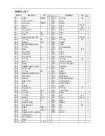
Page 10: ...C ring 19 1 W19 Sleeve 1 W68 Handle Assembly 1 W20 Spring 1 W69 Extension Tool Rest 1 W21 Spindle Pulley Set L R 1 W70 Tool Rest 1 W22 V Belt 625 1 W71 Center 1 W23 C ring 16 1 W72 Shaft 1 W24 Plastic...

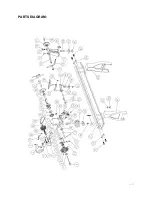
Page 11: ...PARTS DIAGRAM...

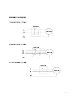
Page 12: ...WIRING DIAGRAM 1 220 240V 50Hz 1 Phase 2 380 400V 50Hz 3 Phase 3 110 120V 60Hz 1 Phase...

Reviews: