background image


10


6.


General safety rules. 


1).


General. 


1-


Never forget that knowledge, awareness and caution are the best way to ensure your 
safety.


2-


Regulations and rules relating to accident prevention, health and safety at work, and 
the operation of vehicles on the public highway must be observed at all times.  


3-


Chapter 4 (Standard operating conditions) of this Instruction Manual, contains basic 
directives that must be followed for the sake of your safety. 


4-


Make sure that no person, animal or obstruction is located near the equipment before 
it is set in motion and throughout its operation or any other manoeuvre. 


5-


Children must never be allowed near the equipment. 


6-


Never carry passengers on the equipment. 


7-


Do not step on the hoods or on any other parts of the equipment, except areas 
provided for this purpose (ladder, platform, and means of access to the work 
station). 


8-


Before carrying out any work on the equipment, ensure that it cannot be started up 
accidentally. 


9-


All controls (ropes, cables, rods, hoses, etc.) must be positioned in the locations 
provided for them so that they cannot accidentally initiate a manoeuvre likely to 
cause an accident or damage. 


10-


Before use and after any adjustment or maintenance, ensure that all protective 
devices are in position and in good condition, and that their latches are engaged. 


11-


Before use, check tightness of screws, nuts, connectors and wheels. Retighten if 
required. 


12-


Do not wear loose clothing, long untidy hair and jewellery that might get caught in 
the moving parts of the equipment.  


13-


Keep your hands, arms and feet well away from any moving parts, even those that 
are slow-moving. Keep well away from moving parts.  


14-


If you detect any unusual noise or vibration, stop the equipment, and identify and 
eliminate the cause of the incident before resuming work. Contact your dealer if 
required. 


Summary of Contents for EPR 23-16

Page 1: ...SPREADER EPR 1000 revs min EPR 23 16 Bogie EPR 23 18 Axle EPR 27 18 Axle EPR 27 20 Axle JEANTIL Rue de la Tertrais ZI La Hauti re BP1 35590 L HERMITAGE France Tel 00 33 0 2 99 64 04 04 Fax 00 33 0 2 9...

Page 2: ...ety related advice 2 Warning symbols This warning symbol identifies important advice that must be followed for your safety When you see this symbol be aware that there is a potential risk of injury re...

Page 3: ...16 Spreader 2 axles EPR 23 18 EPR 27 18 Spreader 3 axles EPR 27 20 SERIAL N COMPLIES WITH 1 Labour regulations 2 The revised European equipment directive N 98 37 EC 3 Revised EMC directive electromag...

Page 4: ...ng stations 7 4 Environmental conditions 7 5 Manufacturer s and user s responsibilities 7 5 Technical characteristics 1 Dimensions 8 2 Stowing diagram 9 6 General safety rules 1 General 10 2 Warning P...

Page 5: ...lves 25 10 Door safety valve 25 11 Short period uses 25 10 Start up and operation 1 Important information 25 2 Loading 26 3 Spreading 26 4 Quantity to spread per hectare 27 11 Additional equipment inf...

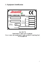
Page 6: ...uction P T A C R ceptionn Masses maximales admissibles Anneau Essieu 1 Essieu 2 kg kg kg kg 20 kg Essieu 3 35590 L HERMITAGE FRANCE Ref 892 770 Manufacturer s plate to EC standards Never remove the ma...

Page 7: ...r the equipment is the tractor s driving station 2 Never leave the driving station when the engine of the tractor and the equipment are operating 3 To access the operating station use the access devic...

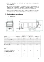
Page 8: ...rer disclaims any responsibility if damage or injury arises from such action 5 Technical characteristics 1 Dimensions EPR Spreader characteristics TYPES EPR 23 16 EPR 23 18 EPR 27 18 EPR 27 20 Working...

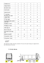
Page 9: ...rward proportional flow with radar Weighing 4 sensors Weighing 6 sensors Following axle Rear steering axle Front and rear steering axle Ball joint ring K80 Tele pressure 2 axles Tele pressure 3 axles...

Page 10: ...form and means of access to the work station 8 Before carrying out any work on the equipment ensure that it cannot be started up accidentally 9 All controls ropes cables rods hoses etc must be positio...

Page 11: ...ictograms remain clean and legible If they are damaged ask for new stickers from the manufacturer or agent 3 If repairs are carried out check that the replacement parts carry the same stickers as thos...

Page 12: ...am Ref 892 446 Placed on metallic casing of primary drive shaft Ref 892 687 Placed on the right and left sides at the back of the spreader Ref 892 703 EP with distributor and rear cover Ref 892 651 Pl...

Page 13: ...7 Placed on the front right and left sides of body Ref 892 453 Placed above right and left tail lights Ref 892 230 Placed at the front of the spreader Ref 892 299 Placed on rear left next to the valve...

Page 14: ...led up the hitch must be locked Check the coupling is correctly locked and in good condition before any movement 7 Check that the equipment s coupling does not create either an overload or poor weight...

Page 15: ...t the speed and direction of rotation of the tractor PTO are compatible with the planned usage of the equipment 6 Maintenance and repair 6 a General 1 Maintenance and repair operations must only be ca...

Page 16: ...nflated to the pressures recommended by the tyre manufacturer See page 22 6 d Electric servicing Before carrying out any work on the electric system disconnect the electric connector 6 e Hydraulic ser...

Page 17: ...iscard in any drainage system used lubricating oil or other substances such as hydraulic oil 2 Collect used fluids in sealed clean containers designed for the purpose Avoid using containers used for f...

Page 18: ...shaft and driving device of the EPAN 7 It is equipped with a declutchable cam limiter 3 Hydraulics 1 See page 16 hydraulic servicing and repairs 2 Read sticker page 11 ref 892 640 3 Spreaders are desi...

Page 19: ...unpriming if you experience problems contact your John Deere dealer 4 Electricity 1 See pages 15 16 and 17 section 6 Maintenance and repair 2 Read sticker page 11 ref 892 640 All types of equipment di...

Page 20: ...ge The oil change of all gearboxes should be carried out at least once a year depending on the frequency of use Quality of oil or equivalent Quantity of oil See table below TYPES Moving floor reductio...

Page 21: ...if necessary 4 When the tensioners are at their maximum for adjusting chain cut two links and tighten again 5 Check the tightness of attachment screws on the moving floor connector bars especially dur...

Page 22: ...lic motor Included in the hydraulic moving floor option 1 The speed of the moving floor s hydraulic motor is electrically controlled The first electric button marked 0 located at the bottom of the ele...

Page 23: ...the spreading device side 8 b Adjustments re calibration 1 To be carried out once if the limiter disengages too often in normal operating conditions i e normally loaded body and standard moving floor...

Page 24: ...tractor engine s speed right down 3 Invert the moving floor s speed to maximum preferably for 10 seconds to bring the heap of manure back towards the front 4 When the heap of manure is cleared from t...

Page 25: ...te or decalibrate screw or unscrew the valve s adjusting screw and control with pressure gauge 10 Door safety valve 1 Valve N 825 246 fitted on the lower port piston side of one of the hydraulic door...

Page 26: ...loader to carry out the loading If this operation is carried out by another person do not stand in the loading area 4 For a regular spreading load the body uniformly 3 Spreading Activating the spreadi...

Page 27: ...n metres 3 Apply the formula below to work out the distance d in metres to cover to empty the load P Example P 8 T known L 4545 M determinated 10 000 2 20 K 35 T ha imposed d P x L K d 8 x 4545 35 103...

Page 28: ...ich should not exceed 60 thermometer of the reservoir indicator MAINTENANCE Empty the reservoir once a year Mineral oil hydro 32 Unil Or equivalent 49 litres Change the cartridge of the pressure filte...

Page 29: ...5 246 fitted on one of the door cylinders is completely open In case of frost check functioning before using the equipment 5 Silage extension FUNCTION The initial volume of the body is increased with...

Page 30: ...r from top to bottom For return slowly open the valve of the pump MAINTENANCE Change oil at least once a year Hand pump capacity 4 litres Mineral oil Hydro 32 Unil Or equivalent 12 Cleaning Cleaning m...

Page 31: ...ting the hose on electronic components the engine or electric connections hydraulic lines and hoses seals filler plug etc 8 Do not use detergent or acid products 9 Wear sufficient protection to avoid...

Page 32: ...tensioner 911006 1 A Tensioning sprocket 911007 1 A Spreading disc 911008 1 A Spreading table 911009 1 A Guillotine door 911010 1 A EPR casings 911011 1 A Moving floor 911012 1 A Hydraulic diagram of...

Page 33: ...33 911016 1 A Hydraulic diagram of tandem braking...

Page 34: ...g distributor Pressure on return 3 Lack of hydraulic power Check pressure of 2 distributor units of the spreader and the tractor s distributor 180 bar Too much pressure loss with dual acting distribut...

Reviews: