


18
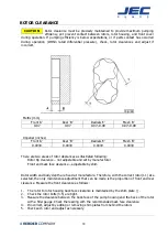
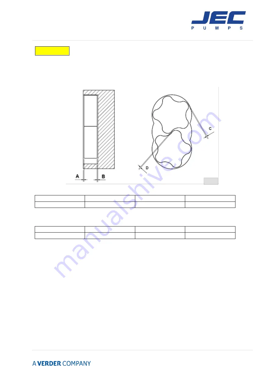
ROTOR CLEARANCE
Rotor clearance must be precisely maintained to provide maximum pumping
efficiency, yet prevent contact between rotors, rotor housing, and front cover
during operation. If pumping efficiency is below expectations, or if parts contact has occurred
during operation (Within rated differential pressure), check, rotor clearances and adjust if
incorrect.
Metric (mm)
Front ‘A’
Rear ‘B’
Radials ‘C’
Mesh ‘D’
0.07
0.07
0.07~0.09
0.07~0.09
Imperial (inches)
Front ‘A’
Rear ‘B’
Radials ‘C’
Mesh ‘D’
0.0039
0.0039
0.0039
0.0039
There are two areas of rotor clearances as illustrated following:
Rotor tip clearance – not adjustable and set by manufacturer
Front and back face clearance – adjustable by shim
Rotor width and body depth are fixed at manufacture. Therefore, with the correct rotor(1.1) size
selected, the only maintenance adjustment that can be made is the proportion of front and rear
clearance. Measure the front clearance as follows:
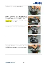
1.
The rotor to rotor housing back face clearance is maintained by the shim plate ( ).
2.
Check the rotor bolts (3.5) are tight.
3. Measure the clearance between the back face of the pump housing and the back of the rotor
with a filler gauge. Check the reading with the recommended back face clearance.
4. If incorrect, adjust by adding or removing shim plates from behind the rotors
5. Check each rotor and adjust as necessary.
CAUTION
Fig. 24
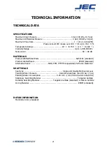
Summary of Contents for AccuLAB Series
Page 1: ...Operating Maintenance Manual JEC AccuLAB Series Rotary Lobe Pumps...
Page 4: ...3...
Page 5: ...4...
Page 6: ...5...
Page 7: ...6...
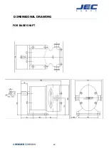
Page 23: ...22 DIMENSIONAL DRAWING FOR BARE SHAFT...
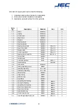
Page 24: ...23 PARTS LIST EXPLODED VIEW...


