background image


20 

GEARBOX ASSEMBLY 


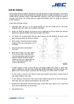
Place the rotor (1.1) on a flat surface. Lubricate the front and rear bearing areas of the drive and 

idle  shafts  with  grease.  Insert  the  shafts  into  the  rotor  splines,  for  support.  Heat  the  front 

bearing to 250

o

F. Place the bearing over the shaft, after the bearing cooled. 


Place the gearbox over the shafts. 


Position the gearbox with wet end up. Insert the front bearing with shaft perpendicularly to the 

gearbox.  There  should  be  a  tight  sliding  fit  between  the  gearbox  and  the  bearing  outer rings. 

Press or soft hammer could be used. 


Place the front bearing and tightened. 


Rear bearing assemblies insert into the rear cover. There should be tight sliding fit. 
 

Heat  the  inner ring  of  the  rear bearing  to  250

o

F.  Place  the  inner ring  over the  shafts  with the 

flange end sliding over the shaft first. 


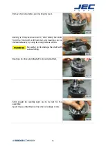
Lubricate the gear area of the shaft and the face of the lock washer, with grease 


Position both shaft gear keys to the 12:00 position. 


Place the gear, lock washer (3.3) and lock nut (3.3) onto the shafts and hand tighten. 


After the gears are installed, turn the shafts to make sure they turn freely and that the rotors 

(1.1) are timed correctly. 


Use a spanner wrench to tighten the gear lock nut (3.3) on the drive shaft. You can install the 

rotors to hold the shafts in place while you tighten the nut. 


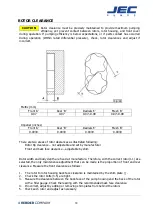
Measure  rolling torque  with no  load on  bearing.  Set  the  torque  wrench  to zero  while rotating, 

this will remove the load caused by the lip seal. 


The  bearing  locknut  should  be  tightened  until  the  rolling  torque  on  the  shaft  measures  the 

values in the following table. 


Tighten the locknut (3.3) on the idle shaft, following the previous steps. 


Measure the shaft endplay to be sure it is zero. If the endplay is not zero, repeat the tightening 

steps. To repeat these steps, the locknut (3.3) will have  to be backed off and the bearing will 

have to be tapped to remove the loadings. 


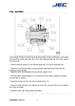
Install the liquid gasket to rear cover quad ring (4.12) and mount the rear cover(1.4) assembly 

over the drive shaft extension onto the gearbox


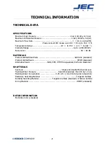
Summary of Contents for AccuLAB Series

Page 1: ...Operating Maintenance Manual JEC AccuLAB Series Rotary Lobe Pumps...

Page 2: ...ranty INSTALLATION Installation Start Up TROUBLESHOOTING Troubleshooting MAINTENANCE Disassembly Inspection Pump housing assembly Shaft and bearing replacement Seal assembly Rotor Clearance Rotor Timi...

Page 3: ...cation beyond the intended use or conversion of the pump without written agreement with the manufacturer shall be deemed to be not in accordance with the intended use The pump may only be started up f...

Page 4: ...3...

Page 5: ...4...

Page 6: ...5...

Page 7: ...6...

Page 8: ...pump DO NOT start the pump until all personnel are clear DO NOT touches the pump or the lines when pumping hot fluids or when performing Clean In Place CIP procedures DO NOT run the pump with BOTH th...

Page 9: ...ing hereunder or for negligence for any and all losses and damages resulting from any cause shall be either the repair or replacement of defective components or pumps verified by JEC In no event inclu...

Page 10: ...n cannot be seen look through the pump case adaptor after takeoff motor shroud Bump means to momentarily apply power to the motor and then immediately remove power 3 Direction of rotating must only be...

Page 11: ...temp Leaks in piping or pump Dissolved gas in product Mechanical noise Excessive weight from piping Pump body distorted Excessive discharge pressure Worn bearing Worn gears Rotor to Rotor contact Inc...

Page 12: ...ad prior to disassembly The pump head may be isolated with inlet and outlet valves And disconnect the suction and discharge piping from the pump Loosen and remove the four cover bolts from the cover R...

Page 13: ...order to remove stationary seals both of seal stopper pin on the top and bottom should be loosened as shown Rotary seal rings are being installed into rotors with rotary seal ring rubber cap Remove s...

Page 14: ...scoring or cracks Replace any seal faces that are damaged 3 Inspect shaft shoulder matched to rotors and other metal parts for wear or damage 4 Inspect rotor galling sign among the rotor housing fron...

Page 15: ...commended torque To tighten the second rotor place the plastic dowel on the opposite side of the rotor and tighten the second rotor bolt to the proper torque Excessive torque could make rotor bolts da...

Page 16: ...ar housing Generally gear housing is no needed for the maintenance disassembly or assembly except filling grease into bearing and gear or maintenance for the gear If gear housing is needed for the mai...

Page 17: ...and bearing can be dismantled easily by using two long bolts as shown Be careful not to damage the shaft with excess hitting WARNING Bearings on drive and idle shaft can be dismantled Shim should be...

Page 18: ...the seal housing into the pump assembly Aligning the flush holes with the tapping in the pump body Install the flush locking adapter O ring onto the adapter 5 1 Install the flush locking adapter 5 1...

Page 19: ...Rotor tip clearance not adjustable and set by manufacturer Front and back face clearance adjustable by shim Rotor width and body depth are fixed at manufacture Therefore with the correct rotor 1 1 si...

Page 20: ...tor timing is determined by the relative location of the two helical gears 3 2 on the shafts 5 Place the wooden dowel between the rotors 6 Bend away the tab of the lock washer 3 3 on one shaft Loosen...

Page 21: ...shaft gear keys to the 12 00 position Place the gear lock washer 3 3 and lock nut 3 3 onto the shafts and hand tighten After the gears are installed turn the shafts to make sure they turn freely and t...

Page 22: ...dB MATERIALS Product Wetted Steel Parts SUS316L standard Product Wetted Seals EPDM standard Alternative Seals NBR FPM PTFE Encapsulated Perfluoro elastomer SHAFT SEALS Seal type Single and Double Mech...

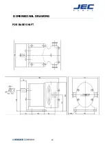
Page 23: ...22 DIMENSIONAL DRAWING FOR BARE SHAFT...

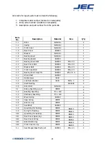
Page 24: ...23 PARTS LIST EXPLODED VIEW...

Page 25: ...over Bolt SUS304 M6 x 15 4 2 5 Bearing Cover Ass y Pin SUS304 5 x 11 5 2 3 1 Drive Shaft SUS304 2 3 2 Helical Gear S45C 2 3 3 Lock Nut Washer S45C M20 x 1 2 3 4 Shaft Bearing 32004XJ 4 3 5 Rotor Bolt...

Page 26: ...eproduced copied duplicated or transmitted in any form or by any means electronic or mechanical photocopying recording for any purpose without any consent or expressed permission of JEC Ltd Copyright...

Reviews: