
8
WARRANTY
TERMS & CONDITIONS
All terms & conditions and prices of sale are based on the applicable JEC price list at the
time an order from Customer is received by JEC and are subject to change without
notice. No assignment of the purchaser’s rights may be made without consent of JEC.
JEC warrants its Product from defects in materials and workmanship for a period of one
(1) year from the shipment date, providing it has been used as recommended and in
accordance with recognized piping practice, and providing it has not been worn out due
to severe service, normal tea and wear or subjected to accident, misuse or improper
maintenance. This warranty extends only to the original Buyer.
This warranty is expressly in lieu of any other warranties expressed or implied, including
but not limited to any implied warranty of merchantability or fitness for a particular
purpose.
All claims must be in writing and must be mailed or delivered by purchaser within thirty
(30) days after purchaser learns of the facts upon which such claim is based. Any claim
not made in writing and within the time period specified above shall be deemed waived.
Purchaser’s sole and exclusive remedy and JEC Ltd.’s maximum liability for claims arising
hereunder or for negligence for any and all losses and damages resulting from any cause
shall be either the repair or replacement of defective components or pumps verified by
JEC.
In no event, including in the case of a claim for negligence, shall JEC Ltd. be liable for
incidental or consequential damages including loss of profits.
No person, including any representative, employee or agent of JEC, is authorized to
assume on behalf of JEC, any liability or responsibility in addition to or different from
that described in this provision. Any and all representations, promises, warranties or
statements that are in addition to or different from the terms of this provision are of no
force or effects.
RECEIVING INSPECTION
Ports are rubber capped at the factory to keep out foreign objects. If covers are missing
or damaged, a thorough inspection of fluid head, by removing pump cover, is
recommended. Be sure pumping head is clean and free of foreign material before
rotating shaft.
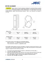
LOSS OR DAMAGE
If your pump has been lost or damaged in transit, immediately file a claim at once with
the delivering carrier and ask for an Inspector to call. The carrier has signed the Bill of
Lading acknowledging that the shipment has been received from us in good condition.
We shall assist you in every way in collecting claims for loss, or damage, however, we
are not responsible for the collection of claims or replacement of material.
Summary of Contents for AccuLAB Series
Page 1: ...Operating Maintenance Manual JEC AccuLAB Series Rotary Lobe Pumps...
Page 4: ...3...
Page 5: ...4...
Page 6: ...5...
Page 7: ...6...
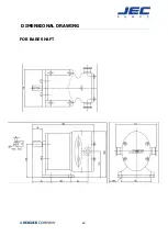
Page 23: ...22 DIMENSIONAL DRAWING FOR BARE SHAFT...
Page 24: ...23 PARTS LIST EXPLODED VIEW...