linear drive type LD100 installation guide version 1.2 page 2 of 3
Loosen this screw to rotate the motor in steps of 90°
to the mounting flange. The motor top should ideally be
in the vertical plane (like drawn) to minimize internal
drag and wear.
The motor top should ideally be in vertical plane (like drawn)
to minimize internal drag and wear.
Compatibility in 12 Volts:
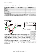
The following table shows the maximum rudder torque that can be generated by Jefa 100 Kgm linier drive in
combination with various autopilot junction boxes.
Autopilot junction box 12 Volt version.
Max. output (Amp.)
Rudder torque (KgM)
Garmin GHP12/GHC10 sailboat APS
40
100
Simrad AC12
12
100
Simrad AC40
40
100
Raymarine X-10
(*1)
10
100
Raymarine X-30
30
100
Nexus-Silva A-1510
(*2)
15
100
NKE gyropilot 2 RVP
(*2)
25
100
Navman G-Pilot
(*2)
20
100
Northstar MCU600
(*2)
20
100
Furuno Navpilot 500/511/520
25
100
*1: We strongly advise to not use the standard X10 autopilot as it delivered without rudder feedback unit. Without rudder feedback unit the autopilot is not aware of actual rudder angle. In
very slow speed conditions or in conditions of a stalling rudder blade, the autopilot doesn't stop with powering the drive unit, running it against the rudder stops and continuing to power the
drive. In time the drive fuse will blow, but mechanical damage can occur in the drive unit which will not be covered under our warranty terms as we can identify this specific damage. We
strongly advise only to use the X10 unit in combination with the optional rudder feedback unit or use the X30 unit.
*2: Special arrangement needed for clutch operation. See separate manual on our FTP server ftp.jefa.com or visit the linear drive product page on www.jefa.com
Mechanical installation:
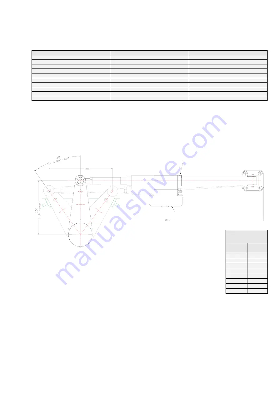
The above illustration shows the correct installation geometry of the linear drive. It's very
important to check if correct rudder stops are fitted (shown in green) limiting the rudder
travel to 2 x 36° (normal for wheel steered systems). The lack of correct rudder stops will
cause the direct drive to act as travel limiter, resulting in damage to the internal gears. The
linear drive has a maximum travel of 303 mm, so there is 4 mm of spare travel each side
assuring a free run.
It’s advisable to mount the drive with the motor pointing sideways and
not up or downwards (like in above illustration) as this position generates less friction and
ware over time.
On most cable steered boats, the rudder travel is 2 x 40° and on some tiller steered boats
the rudder angle is even bigger. Please revert to the table at the right for the correct pin centres in these cases.
Please note that the maximum achievable rudder torque will be lower when shorter centres are used. For
example: The maximum rudder torque for the 50° setup will be 192/250*100= 77 KgM instead of the 100 KgM
with the 36° setup.
Operating centres for
non standard rudder
angles
Output
centre
Tiller
centre
36°
250
38°
239
40°
229
42°
220
44°
212
46°
204
48°
198
50°
192


