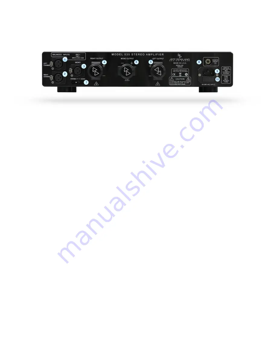
REAR PANEL CONNECTIONS
1.
INPUT:
Left Channel Balanced XLR: Use XLR to RCA input adapter (not included)
for use with RCA interconnects.
2.
INPUT:
Right Channel Balanced XLR; Use XLR to RCA input adapter (not included)
for use with RCA interconnects.
3.
INPUT:
Bridged Mono XLR; Use XLR to RCA input adapter (not included) for use
with RCA interconnects.
4.
LOUDSPEAKER OUTPUT RIGHT CHANNEL
:
Connect to right Loudspeaker, 2 to 16
ohm impedance, for Stereo Operation.
5.
LOUDSPEAKER
OUTPUT LEFT CHANNEL:
Connect to left Loudspeaker, 2 to 16
ohm impedance, for Stereo Operation.
6.
LOUDSPEAKER MONO OUTPUT:
Connect to Loudspeaker, 4 to 16 ohm
impedance, for mono Operation.
7.
STEREO/BRIDGED MODE SWITCH:
Configures Model 535, as either a stereo or
mono amplifier. When configured as a single mono amplifier, the overall gain of
the amplifier is automatically adjusted to maintain the same gain as in stereo
operation.
8.
REMOTE ON/OFF:
A 1/8” (3.5 mm) mini-plug jack is provided on the rear panel of
the Model 535 for remotely switching the amplifier between Operational and
Standby modes.
Applying a continuous 6 to 15 volts DC to the connector will
override the front panel power button and place the amplifier into operational
mode.
The Model 535 operational mode can also be controlled by another audio
component with the proper circuitry, through the remote on/off connector.
Figure 2:
Rear Panel Connections
!
12


