background image


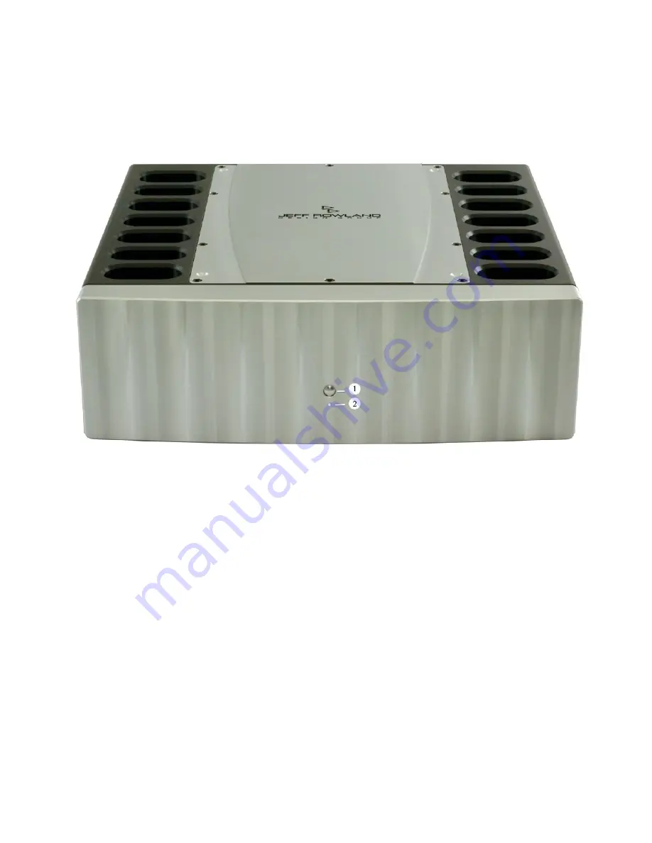
FRONT PANEL


1.

FRONT PANEL POWER BUTTON.


Press this button to operate the ampli

er. Press again to place the 

ampli

er in Standby mode.

2.

POWER INDICATOR LAMP


This light will illuminate when the ampli

er is operational.

Figure 1: 

Front Panel

PAGE   10

Summary of Contents for 735

Page 1: ...Model 735 MONOBLOCK AMPLIFIER Operational Manual Jeff Rowland Design Group 2020 All Rights Reserved...

Page 2: ...d 3 wire grounded AC cable ground terminal is defeated or lifted or the unit is connected to a 2 wire ungrounded AC outlet The MODEL 735 MONOBLOCK AMPLIFIER is designed to perform optimally with no ad...

Page 3: ...with Jeff Rowland Design Group Inc Said determination shall be made as soon as possible following receipt of the product Jeff Rowland Design Group Inc may at its option require from the purchaser val...

Page 4: ...ty exclusions may apply Contact your dealer or Jeff Rowland Design Group Inc for information regarding our commercial warranty policies GUIDE USE This guide is designed to make installing and using th...

Page 5: ...gain the maximum performance and ease of use for which this amplifier was designed Please note that your MODEL 735 MONOBLOCK AMPLIFIER serial number begins with the letters SD Please include this num...

Page 6: ...TABLE OF CONTENTS Special Design Features 6 Maintenance and Care 8 Unpacking and Placement 9 Initial Inspection 9 Unpacking 9 Front Panel 10 Rear Panel 11 Speci cations 12 PAGE 5...

Page 7: ...dynamic signal conditions HIGH CURRENT COPPER BUS BARS High current dual polarity ultra low impedance copper bus bars distribute both power supply input current and signal output current virtually eli...

Page 8: ...AC power inlet accepts a wide variety of after market high performance power cables FRONT PANEL STANDBY BUTTON Illuminated front panel push button switches the amplifier into standby mode 0 3 watt con...

Page 9: ...6 MONTHS BEFORE ATTEMPTING TO CLEAN IT THIS WILL PREVENT SMALL SCRATCHES FROM MARRING THE SURFACE BEFORE THE SURFACE COATING HAS HAD A CHANCE TO HARDEN COMPLETELY WARNING THE FRONT PANEL OF THE UNIT...

Page 10: ...aler immediately We strongly suggest that you save all of the packing materials If the amplifier is returned to your dealer or Jeff Rowland Design Group the original packing materials must be used for...

Page 11: ...ANEL POWER BUTTON Press this button to operate the ampli er Press again to place the ampli er in Standby mode 2 POWER INDICATOR LAMP This light will illuminate when the ampli er is operational Figure...

Page 12: ...Install the positive usually red loudspeaker cable spade terminal to the positive binding post and the negative usually black spade terminal to the negative binding post Secure the loudspeaker connec...

Page 13: ...t transformer Damping Factor 500 20 Hz 20 kHz Overall Gain Bal or Unbal 26 dB Common Mode Rejection Ratio 90 dB 20 Hz 20 kHz Absolute Phase Non inverting Pin 2 Positive Inputs Balanced XLR Outputs 2 p...

Reviews: