h
7
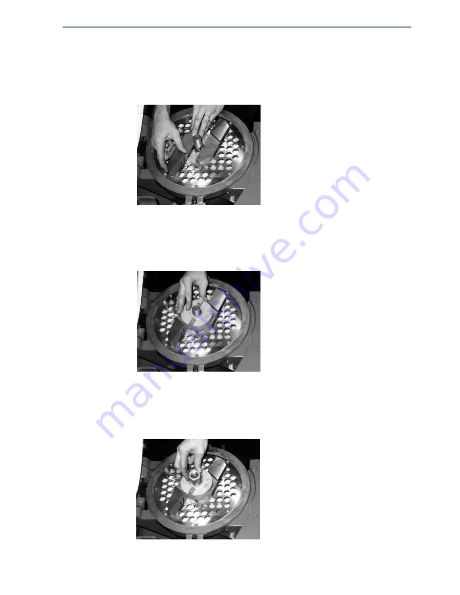
Cutting System Maintenance – Step 4
Place the cutter blades on the keyed seats of the ejector so that the numbers im-
printed on them line up with the correct position on the ejector. Make sure that
the long horizontal adjusting screw in the end of each blade has been withdraw
sufficiently to allow the cutter blades to extend further than required. Do NOT
loosen the short grubscrew which retains the nylon locking pad.
Cutting System Maintenance – Step 5
Place the agitator collar over the spindle and check that the keys locate between
the cutter blades. There are different collars but the key system is the same.
Cutting System Maintenance – Step 6
Screw the spindle nut into place, checking that all the various component parts
of the Cutting System are located correctly.
Figure 6. Locating the Cutter Blades
Figure 7. Locating the Agitator Collar
Figure 8. Adding the Spindle Nut


