USER MANUAL
JEFCIND200L-4.0
200L
BELT DRIVEN AIR COMPRESSOR
•
4HP
•
10Bar
•
230V
~
50Hz
USER MANUAL
JEFCIND200L-4.0
200L
BELT DRIVEN AIR COMPRESSOR
•
4HP
•
10Bar
•
230V
~
50Hz
www.jeffersontools.com
www.jeffersontools.com
4
5
•
200L
Belt-driven compressor suitable for professional workshops
•
Fitted with a heavy duty
single-phase
4HP
motor
•
Heavy-duty cylinders with alloy heads for improved heat dissipation
•
Pressure regulator with moisture trap
•
Fitted with 4x anti-vibration feet
•
Drive guards offer protection to the fly-wheel and belt assembly
•
Powder-coated tank
•
Twin pressure gauges showing tank and working pressure
•
Welded tank fully-compliant with the latest European manufacturing & safety standards
SPECIFICATIONS
JEFCIND200L-4.0
Tank Capacity:
200L
Power:
4.0HP / 3.0kW
Input Voltage ~ Frequency:
230V ~ 50Hz / 16A
Maximum Pressure:
10bar (145psi)
Pump Speed:
945rpm
Cylinders:
3
Air Displacement:
15.9 cfm (452 L/min)
Free Air Delivery:
9.4 cfm (266 L/min)
Guaranteed Sound Power:
96 dB LWA
Weight:
NW: 146kg / GW: 182kg
Dimensions:
1365 x 477 x 1033mm
INTRODUCTION
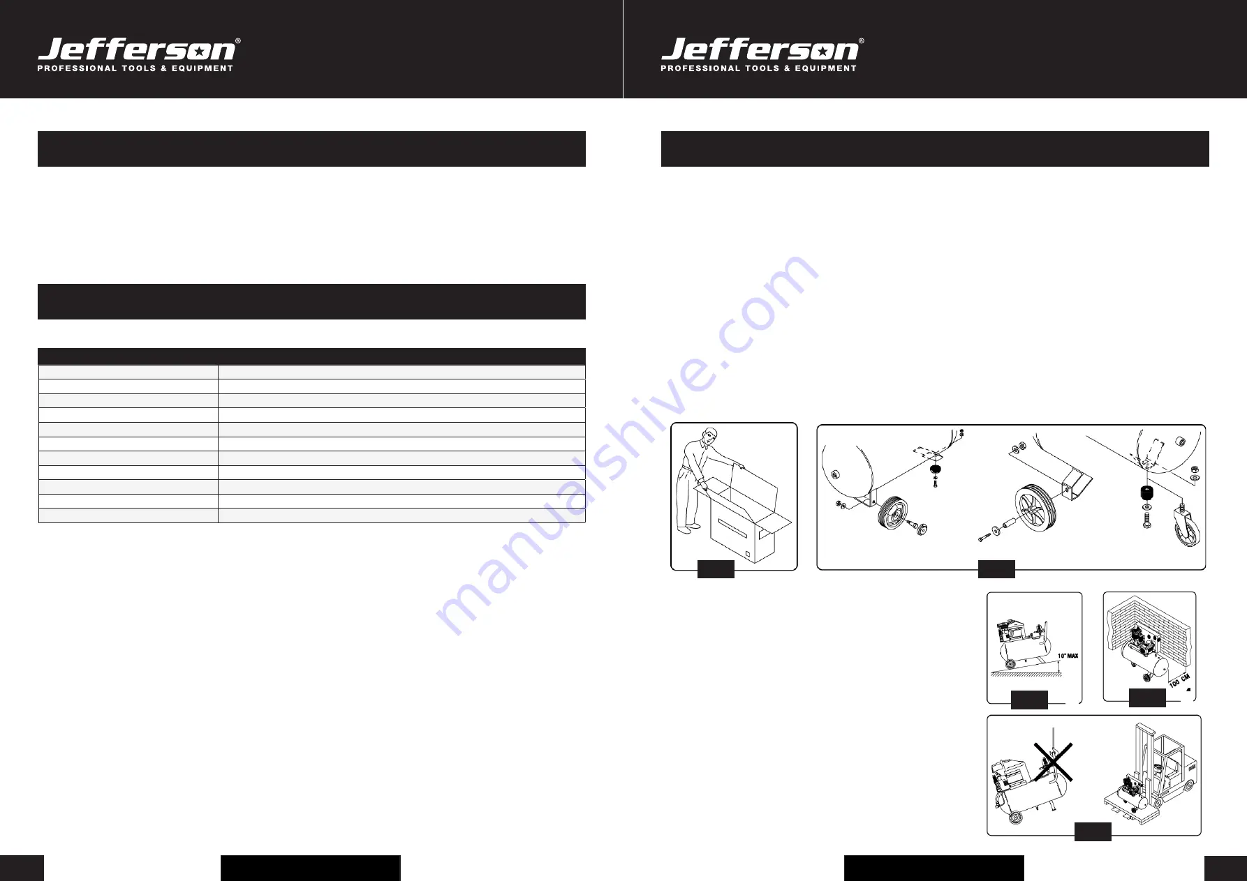
Upon receipt of the compressor, ensure all components are present and have remained undamaged in transit..Retain the packing materials and
packaging in case future transportation of the compressor is necessary. We recommend that the packaging is kept, at least within the period of
the guarantee (
Fig.1
).
WHEELS AND ANTI-VIBRATION FOOT
Pass the 15mm bolt through the wheel, the compressor's frame and secure with the 15mm nut. Locate the wheel onto the axle and secure in
place with the internal self locking washer (single use only) (
Fig.2
).
AIR FILTER
If not already fitted, remove the transit bung from the top of the head and screw the air filter assembly into position.
OIL BREATHER
•
For transportation purposes the oil breather is supplied in a separate bag.
•
Read the caution plate and take off the plastic bung from the crankcase, add oil and then assembly the oil breather.
•
The plastic bung should be retained for future use should it be necessary to transport the unit.
WARNING:
Never operate the compressor with only the plastic transportation bung fitted. Under normal use internal pressure can expel the bung along with
oil from the head, possibly leading to damage.
PLEASE NOTE THE FOLLOWING PHOTOGRAPHS & INSTRUCTIONS ARE FOR REFERENCE ONLY AND MAY DIFFER FOR YOUR
COMPRESSOR MODEL. PLEASE CONTACT JEFFERSON TOOLS IF YOU NEED ANY ADVICE ON THE ASSEMBLY PROCEDURE.
Position the compressor on a flat surface or with a maximum permissible
inclination of 10° (
Fig.3
), in a well aired place, protected against atmospheric
agents and not in a place subject to explosion hazard.
If the surface is inclined and smooth, check if the compressor moves while in
operation – if it does, secure the wheels with two wedges.
To ensure good ventilation and efficient cooling, the compressor’s belt guard must
be at least 100cm from any wall (
Fig. 4)
.
Ensure that the compressor is transported correctly, do not overturn it or lift it with
hooks or ropes (
Fig. 5
)
After removing the packing materials, check to ensure the product is in perfect
condition and that there are no damaged parts from transit. If in doubt, do not use
the product and notify your Jefferson Dealer.
The packaging materials (cardboard, plastic bags, polystyrene, etc), must be
disposed of in an appropriate manner and recycled where possible. These
materials must not be left within the reach of children as they are potential
sources of danger.
UNPACKING & ASSEMBLY
Fig.3
Fig.4
Fig.2
Fig.1
Fig.5


