background image

4

USER MANUAL

 JEFLD2001/50 

 JEFLD2001/50110

50L 

AIR  COMPRESSOR

www.jeffersontools.com

  1. INTRODUCTION


• 

Aluminium head with cast-iron cylinder ensures durability & long-running operation  

• 

Direct-drive assembly with pump head connected to heavy-duty induction motor for reliable and quiet operation 

• 

Suitable for general-purpose workshop applications 

• 

Welded tank fully-compliant with the latest European manufacturing & safety standards 

• 

Fitted with an automatic pressure cut-out switch with twin gauges displaying tank and working pressures 

• 

Equipped with transportation handle, front rubber mounted feet and rear wheels to assist manoeuvrability 

• 

Powder-coated finish on the tank provides protection against corrosion  

  2. SPECIFICATIONS


JEFLD2001/50

JEFLD2001/50110

Tank Capacity:

50L

50L

Input Voltage ~ Frequency:

230V ~ 50Hz

110V ~ 50Hz

Motor Output: 

2HP

2HP

Plug Type / Rated Supply:

UK 3-Pin / 13A

UK 3-Pin / 16A

Pump:

Single Cylinder • 2900rpm  

Single Cylinder • 2900rpm  

Air Displacement: 

7cfm (191 l/min)

7cfm (191 l/min)

Free Air Delivery: 

97 l/min (3.4cfm)

97 l/min (3.4cfm)

Maximum Pressure:

8bar  (116psi) 

8bar  (116psi) 

Wheel Diameter:

150mm

150mm

Lubrication:

Semi-Synthetic SAE30 (Optional 15W-40) • 220 cc

Semi-Synthetic SAE30 (Optional 15W-40) • 220 cc

Weight:  

NW:36kg / GW: 39kg

NW: 36kg / GW: 39kg

Box Dimensions:

795 x 365 x 710cm

795 x 365 x 710cm

  3. UNPACKING & ASSEMBLY 


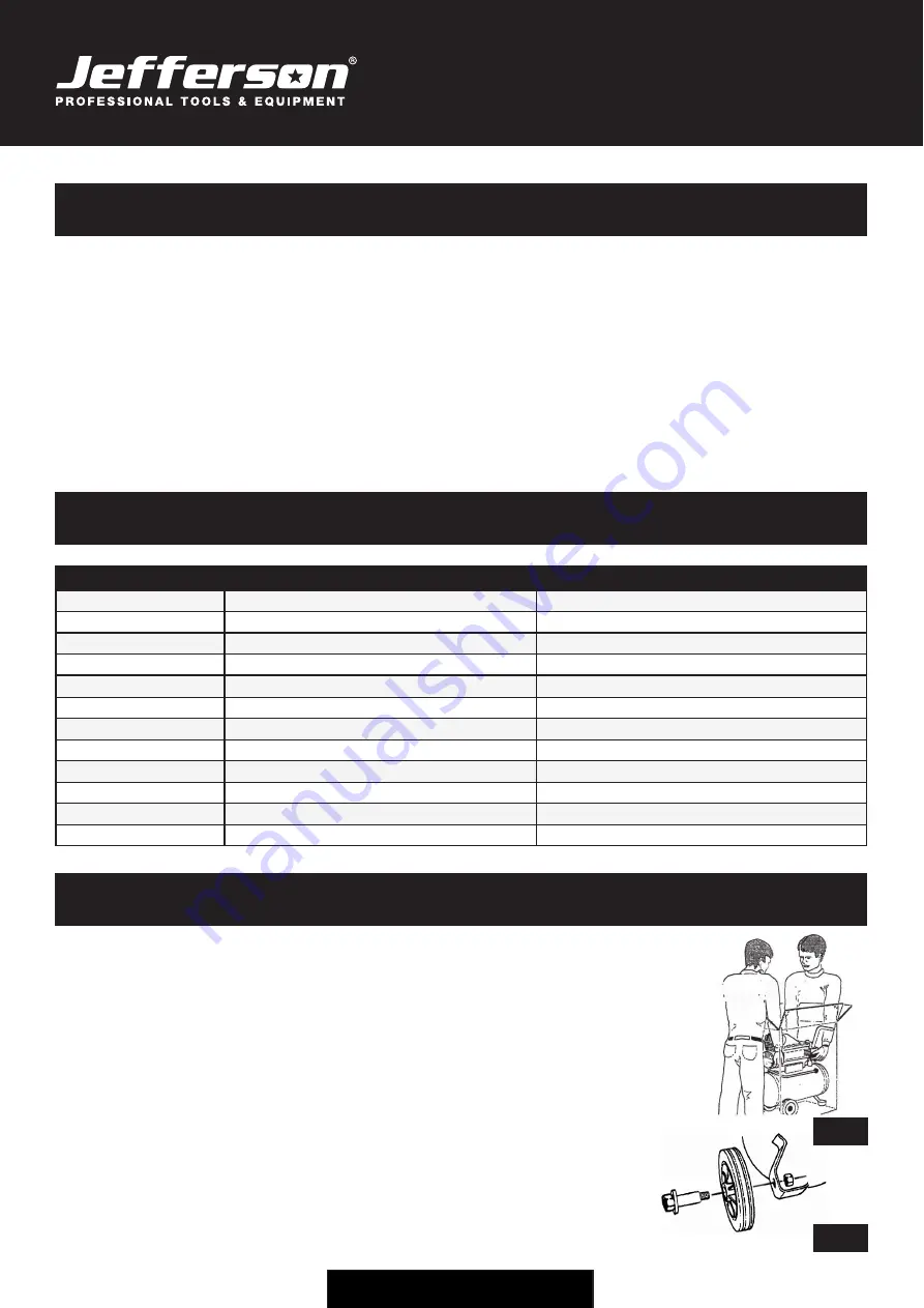
Remove compressor from the carton: 


Wear protective gloves and cut the outer strapping with side cutters.  
Remove the staples with long nose pliers and open the top flaps. With assistance, carefully lift the compressor 
and place it on the work surface (See Fig.1). 

Carefully inspect the equipment for any missing items or damage incurred during transit. 

If anything is found to be missing or damaged contact your nearest Jefferson Dealer. 

We recommend that you store the packaging for the duration of the warranty period. If necessary, it will be 
easier to return the compressor to the service centre.

Fit the wheels (See Fig.2) and front feet, remove the transport bung from the oil filler hole and replace 
with the dipstick / breather supplied. Fit  the air filter and add oil to the pump, if necessary.

Confirm that the mains voltage corresponds with the voltage shown on the compressor's 
data / specification plate. 


Fig.1  


Fig.2  


Summary of Contents for JEFLD2001/50

Page 1: ...User Manual v 1 1 JEFLD2001 50 JEFLD2001 50110 COMPRESSOR 50L ...

Page 2: ...e safe operation and maintenance of the compressor Some illustrations in this Instruction Manual may show details or attachments that differ from those on your own compressor Contact your nearest Jefferson Dealer if you are unsure about any information included in this manual or require any additional information about the safe use operation or maintenance of this equipment ...

Page 3: ...ns 4 Unpacking Assembly 4 Before First Use 5 General Safety Guidelines 6 Electrical Safety 7 Warning Labels 8 Operation Guide 9 Troubleshooting 10 Maintenance 10 Parts Diagram Main Assembly 11 Parts List Main Assembly 12 Parts Diagram Pump 13 Parts List Pump 14 EC Declaration of Conformity 15 Limited Warranty Statement 16 ...

Page 4: ...min 3 4cfm 97 l min 3 4cfm Maximum Pressure 8bar 116psi 8bar 116psi Wheel Diameter 150mm 150mm Lubrication Semi Synthetic SAE30 Optional 15W 40 220 cc Semi Synthetic SAE30 Optional 15W 40 220 cc Weight NW 36kg GW 39kg NW 36kg GW 39kg Box Dimensions 795 x 365 x 710cm 795 x 365 x 710cm 3 UNPACKING ASSEMBLY Remove compressor from the carton Wear protective gloves and cut the outer strapping with side...

Page 5: ...clines in excess of 15 degrees Serious damage to pump components may result from insufficient lubrication Never use the air compressor on a rooftop or elevated position that could allow the unit to fall or be tipped over Use additional air hose for elevated jobs 4 3 Check power supply is correct for this compressor It is essential that the air compressor has an adequate power supply Always utilize...

Page 6: ...te the compressor in damp or wet locations 5 Disconnect the compressor Always disconnect the compressor from the power source and remove the compressed air from the air tank before servicing inspecting maintaining cleaning replacing or checking any parts 6 Avoid unintentional starting Do not carry the compressor while it is connected to its power source or when the air tank is filled with compress...

Page 7: ...pressed air from the air tank 25 Never touch hot surface To reduce the risk of burns do not touch tubes heads cylinder and motors 26 Do not direct air stream at body Risk of injury do not direct air stream at persons or animals 27 Drain tank Drain tank daily or after 4 hours of use Open drain fitting and tilt compressor to empty accumulated water 28 Do not stop compressor by pulling out the plug U...

Page 8: ...nition thinners improperly secured could get into the hands of children or other unqualified persons Good air flow is important as both the motor and com pressor unit are air cooled Restrictions to or insufficient air flow will cause overheating Never spray paint in a confined area with the air compres sor Operate the air compressor in well ventilated areas free from obstructions Equip areas with ...

Page 9: ...ressure gauge The compressor will now operate automatically The pressure switch stops the motor when the maximum tank pressure is reached and restarts it when the pressure falls below the minimum threshold approx 2 bar 29psi less than the maximum pressure Stopping The Compressor Stop the compressor by moving the main switch to the OFF position The compressed air inside the compressor head will flo...

Page 10: ...ain using the pressure switch This will vent air from the delivery tube The compressor sounds like it is trying to start motor makes a humming noise The capacitor is faulty Stop the compressor and contact a specialized service technician Air leaks from the safety valve at pressures less than 10 bar The safety valve is faulty Replace the Safety valve 10 MAINTENANCE WARNING When doing maintenance yo...

Page 11: ...11 USER MANUAL JEFLD2001 50 JEFLD2001 50110 50L AIR COMPRESSOR www jeffersontools com 11 PARTS DIAGRAM MAIN ASSEMBLY ...

Page 12: ...1 Hex Nut 5 1 Rubber Foot 6 2 Plate Washer 7 2 Hex Bolt Thread 8 1 Mini Ball Valve 9 2 Wheel 10 2 Washer 11 2 Plug 12 6 Hex Screw 13 4 Plate Washer 14 1 Check Valve Cap 15 2 Sleeve 16 1 Tubing 17 1 Bushing 18 1 Sleeve 19 1 Sleeve Lock Nut 20 1 Rilsan Tube 21 1 Pressure Gauge 22 1 Pressure Switch 23 1 Safety Valve 24 1 Nipple 25 1 Pressure Regulator 26 1 Ball Valve 27 1 Pressure Gauge ...

Page 13: ...13 USER MANUAL JEFLD2001 50 JEFLD2001 50110 50L AIR COMPRESSOR www jeffersontools com 13 PARTS DIAGRAM PUMP ...

Page 14: ...ng 22 1 Oil Sight Glass 23 4 Head Bolt 24 1 O Ring 25 1 Air Breather 26 1 Hex Nut 27 1 Washer Spring 28 1 Capacitor 29 1 Overload Protector 30 1 Conrod Part Number Quantity Description 31 2 Circlip 32 1 Piston Pin 33 1 Piston 34 1 Piston Ring Rod 35 1 Piston Ring 36 1 Compression Ring 37 1 Piston Ring Kit 38 1 Piston Kit 39 1 Gasket Cylinder 40 1 Cylinder 41 2 Stud Bolt 42 2 Hex Nut 43 1 Gasket Va...

Page 15: ...ed Low Voltage Directive Equipment Category Air Compressor Item 8 Product Name Model 50L Compressor 230v JEFLD2001 50 110V JEFLD2001 50110 The conformity assessment procedure followed was in accordance with Annex VI of the Outdoor Noise Directive Measured Sound Power Level 96dB Guaranteed Sound Power Level 96dB EU Member State United Kingdom Signed by Stephen McIntyre Position in the company Opera...

Page 16: ...rsontools com warranty and completing the online form Online warranty registration is recommended as it eliminates the need to provide proof of purchase should a warranty claim be necessary Warranty Repair Should Jefferson confirm the existence of any defect covered by this warranty the defect will be corrected by repair or replacement at an authorized Jefferson dealer or repair centre Packaging F...

Page 17: ...in need of repair and any repairs needed are covered by the warranty policy In order to qualify for warranty cover all equipment presented must have been used serviced and maintained as instructed in the user manual Where repair is not covered by the warranty a quotation for repair labour costs and return delivery will be sent to the customer normally within 7 working days Note If the repair quota...

Page 18: ...18 USER MANUAL JEFLD2001 50 JEFLD2001 50110 50L AIR COMPRESSOR www jeffersontools com Notes ...

Page 19: ...19 USER MANUAL JEFLD2001 50 JEFLD2001 50110 50L AIR COMPRESSOR www jeffersontools com ...

Page 20: ...ess Park Chester United Kingdom CH4 9QR Tel 44 0 1244 646 048 Email sales jeffersontools com IMPORTANT SAFETY FIRST Before attempting to use this product please read all the safety precautions and operating instructions outlined in this manual to reduce the risk of fire electric shock or personal injury www jeffersontools com ...

Reviews: