


USER MANUAL
JEFBG6 • JEFBG8
INDUSTRIAL
BENCH GRINDER
www.jeffersontools.com
9
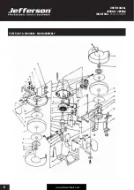
PARTS LIST & DIAGRAM - PUMP ASSEMBLY
#
Description
#
Description
1
Left protective cover
33
Motor Shaft
2
Snap ring
34
Machine frame (right side)
3
Left shaft nut
35
Screw
4
Recessed head screw
36
Cable support
5
Securing Disc / Counter-disc
37
Cable clamp
6
Ring
38
Cable covering
7
Grinding Wheel
39
Stator
8
Mounting for spark guard (left side)
40
Cable lug
9
Spark guard
41
Rubber cover for cable lug
10
Nut
42
Mounting plate
11
Plate
43
Power Switch
12
Locking Screw
44
Washer
13
Fastening screw
45
Screw
14
Locking Screw
46
Mounting for spark guard (right side)
15
Snap rng
47
Locking screw
16
Inner Cover for grinding wheel
48
Snap dng
17
Glass guard support (left side)
49
Earthing point
18
Plate
50
Star ring
19
Hex bolt
51
Capicitor
20
Screw
52
Clamping
21
Adjustable prptective cover
53
Cable lug
22
Workpiece support (left side)
54
Rubber cover
23
Fastening nut
55
Wokpiece support (right side)
24
Machine frame
56
Inner cover for grinding wheel (right side)
25
Screw
57
Screw
26
Snap dng
58
Washer
27
Shaft bearing
59
Bottom Cartridge
28
Power Cable with plug
60
Paper Ring
29
Screw
61
Grinding wheel
30
Main lead cleat
62
Right shaft nut
31
Locking screw
63
Right protective cover
32
Washer