USER MANUAL
JEFC050L08B Series
50L
AIR COMPRESSOR
•
2HP
•
8Bar
•
Direct Drive
www.jeffersontools.com
4
•
Aluminium head with cast-iron cylinders ensures durability & long-running operation
•
Direct-drive assembly with pump head connected to heavy-duty induction motor for reliable and quiet operation
•
Suitable for general-purpose workshop applications
•
Welded tank fully-compliant with the latest European manufacturing & safety standards
•
Fitted with an automatic pressure cut-out switch with twin gauges displaying tank and working pressures
•
Equipped with transportation handle, front rubber mounted feet and rear wheels to assist manoeuvrability
•
Powder-coated finish on the tank provides protection against corrosion
SPECIFICATIONS
JEFC050L08B-230
JEFC050L08B-110
Tank Capacity:
50L
50L
Input Voltage ~ Frequency:
230V ~ 50Hz
110V ~ 50Hz
Motor Output:
2HP
2HP
Plug Type / Rated Supply:
UK 3-Pin / 13A
UK 3-Pin / 16A
Pump:
Single Cylinder • 2900rpm
Single Cylinder • 2900rpm
Air Displacement:
7cfm (191 l/min)
7cfm (191 l/min)
Free Air Delivery:
97 l/min (3.4cfm)
97 l/min (3.4cfm)
Maximum Pressure:
8bar (116psi)
8bar (116psi)
Wheel Diameter:
150mm
150mm
Lubrication:
Semi-Synthetic SAE30 (Optional 15W-40) • 220 cc
Semi-Synthetic SAE30 (Optional 15W-40) • 220 cc
Weight:
NW: 36kg / GW: 39kg
NW: 36kg / GW: 39kg
Equipment Dimensions:
760 x 395 x 680mm
760 x 395 x 680mm
Carton Dimensions:
795 x 365 x 710cm
795 x 365 x 710mm
UNPACKING & ASSEMBLY
Remove compressor from the carton:
Wear protective gloves and cut the outer strapping with side cutters.
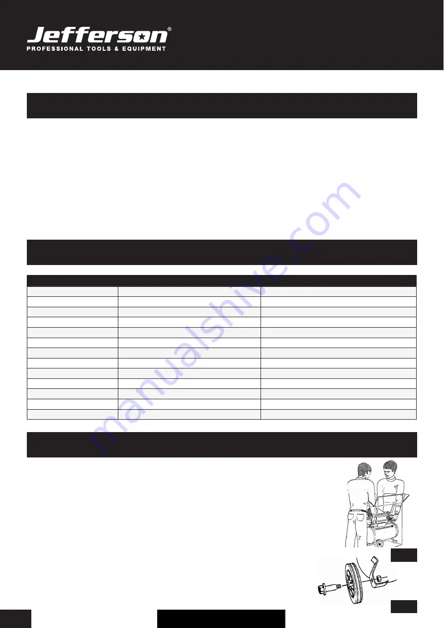
Remove the staples with long nose pliers and open the top flaps. With assistance, carefully lift the compressor
and place it on the work surface (See Fig.1).
Carefully inspect the equipment for any missing items or damage incurred during transit.
If anything is found to be missing or damaged contact your nearest Jefferson Dealer.
We recommend that you store the packaging for the duration of the warranty period. If necessary, it will be
easier to return the compressor to the service centre.
Fit the wheels (See Fig.2) and front feet, remove the transport bung from the oil filler hole and replace
with the dipstick / breather supplied. Fit the air filter and add oil to the pump, if necessary.
Confirm that the mains voltage corresponds with the voltage shown on the compressor's
data / specification plate.
INTRODUCTION
Fig.1
Fig.2


