USER MANUAL
MULTI-PURPOSE LADDER
V1.2
www.jeffersontools.com
3
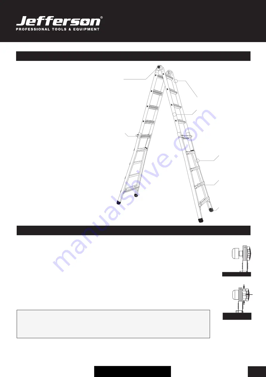
EQUIPMENT IDENTIFICATION
The Jefferson Multi-Purpose Ladder is made
up of 3 main components:
1 Inner Ladder Section and 2 Outer Ladder
Sections.
The inner and outer sections work together
using hinge locks and lock tabs which enable
you to adjust and extend the ladder into
different lengths and positions.
The 3 main working configurations are:
1.
A-Frame Stepladder
2.
Uneven A-Frame Stepladder
3
. Extension Ladder
See Page 4 for further information on setting up
the ladder to work in each configuration.
Push knob
locking hinge
•
Inner ladder
section
•
Ladder
side rail
Spring loaded
•
'J' lock
•
Outer
ladder section
•
Rung
•
Anti-slip feet
•
OPERATION GUIDE
Push Knob Hinge Locks - Change your ladder’s shape
The ladders inner section allows the ladder to be folded into 3 set positions; extension ladder, twin stepladders, and storage.
Each of these configurations is made possible by the push knob locking hinge located on each side of the ladder.
To adjust the angle of the ladder:
1) With the center hinges in the closed position (Fig. 1) push the knobs with the palm of your hand directly onto the centre
of the ladder, they will stay in the open position.
2) In the open position (Fig. 2) the ladder angle can be adjusted.
Note: The open position can be verified by the exposed triple inner posts on the push knob.
3) When the ladder reaches any of the 3 set positions, the push knobs will automatically spring back into the closed position.
4) To close ladder to the folded position, repeat steps 1-3.
WARNING!
• Serious injury or death could result if supporting hinges are NOT LOCKED when ladder in use.
• Make certain supporting hinges are LOCKED before using ladder EACH TIME.
FIG.1 CLOSED
FIG.2 OPEN
(Triple Inner Posts)


