background image

12

USER MANUAL

JEFMIG185-A – JEFMIG210-A 

185A MIG WELDER - 230V 50Hz

210A MIG WELDER - 230V 50Hz

www.jeffersontools.com

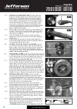
A spool of welding wire is positioned on the welder’s spool holder and automatically 
fed through an insulated liner in the torch to the tip. The torch assembly consists of a 
switch, liner, gas hose, and control cable. The switch activates the wire feed roller and 
the gas flow. Conversely, releasing the switch stops the wire feed and gas flow. The 
weld current is transferred to the electrode (the wire) from the contact tip at the end of 
the torch. A gas cup fits over the contact tip to direct the gas flow towards the weld 
ensuring that the arc welding process is shielded from oxidising air contaminates. The 
shielding gas also assists heating of the weld materials. (The welder can also be used 
in gasless mode using flux cored wire). The torch is connected to the positive side of 
a DC rectifier, and the negative clamp is attached to the workpiece.

IMPORTANT: Should you have no welding experience, we recommend you seek 
training from an expert source to ensure your personal health & safety. Good 
Mig welding may be achieved only with continued, supervised practice.

7. 1  

 PREPARATION FOR WELDING 

IMPORTANT: BEFORE YOU COMMENCE, MAKE SURE THE MACHINE IS 
SWITCHED OFF AT THE MAINS. IF WELDING A CAR, DISCONNECT THE 
BATTERY OR FIT AN ELECTRONIC CIRCUIT PROTECTOR. ENSURE YOU 
HAVE READ & UNDERSTOOD THE ELECTRICAL SAFETY INSTRUCTIONS 
IN SECTION 3.

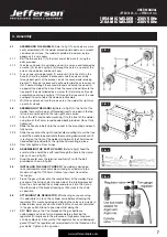
7.1.1  


Connecting the Earth Lead.


To ensure a complete circuit, the earth lead must be securely attached to the 
work piece that is to be welded. 
a) Best connection is obtained by grinding clean the point of contact on the 
workpiece before connecting the earth clamp. 
b) The weld area must also be free of paint, rust, grease, etc. 
c) When welding a vehicle, be sure the vehicle battery is disconnected or fit 
an Electronic Circuit Protector available from your Jefferson dealer.

7.1.2 


 Power Output switch.

 Set the switch to position 1 or 2 for welding up to 

2mm thickness. Use settings 3,4,5,6 for thicker welds.

7.1.3  

 Setting the welder controls.

 In principle, the lower the amperage required, 

the slower the wire speed. See setting chart for voltage and corresponding 
wire speeds. Note: these settings are only a guide and will vary according to 
the operators experience.

7.1.4  


Welding mild steel.

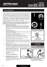
 To weld mild steel you can use CO² gas for most tasks 

where spatter and the high build up of weld do not pose a problem. Welding 
with a long arc reduces penetration and widens the arc. This in turn results 
in more spatter. A long welding arc can be appropriate for welding butt joints 
in thin materials. Welding with a short arc, at the same weld settings, results 
in greater penetration and a narrower weld 
and reduces the amount of spatter. To 
achieve a consistent spatter free and flat 
weld, you must use an Argon/CO² mixture.

7.1.5  


To weld aluminium use:


3

 Argon gas, 

3

 0.8mm Contact Tip (MIG927), 

3

 0.8mm Aluminium Wire, (MIG/2KAL08).

7.1.6  


Overload Protection.

 Thermostatic 

overload protection is provided. When an 
overload has occurred, leave the unit to 
cool. The thermostat will automatically reset 
the unit when the temperature has returned 
within limits

7. MIG / MAG Welding

Settings shown as a guide only

Wire 0.6mm Steel 

Argon / CO

2

 Mix

Voltage Step

1

2

3

4

5

6

Wire Speed

5

6

7

8

9 10

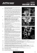
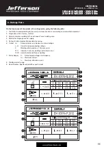
Above: Polarity settings for 

welding without gas and with gas

Summary of Contents for JEFMIG185-A

Page 1: ...User Manual v 1 1 JEFMIG185 A JEFMIG210 A...

Page 2: ......

Page 3: ...he product and prior to any maintenance tasks By following all the general safety instructions contained in this manual you will help to ensure operator safety and extend the potential lifespan of the...

Page 4: ...rced Air Torch Euro Non Live BINZEL ERGO 15 2 2 Introduction Specification 3 1 ELECTRICAL SAFETY WARNING It is the user s responsibility to read understand and comply with the following You must check...

Page 5: ...able extension reel is used it should be fully unwound before connection A cable reel with an RCD fitted is recommended since any product which is plugged into the cable reel will be protected The cro...

Page 6: ...oes Turn voltage switch to OFF when not in use DO NOT operate the welder if it or its cables are damaged and DO NOT attempt to fit any unapproved torch or other parts to the welder unit DO NOT get wel...

Page 7: ...hten yet 4 2 2 Slide the handle tube 2 into the socket in the mounting and push fully home 4 2 3 Slide the socket on the right hand handle mounting 3 over the free end of the handle tube and rotate th...

Page 8: ...r Failure to do this could cause the wire to slip and or bind 4 7 1 Unscrew the locking knob from the end of the spool holder see fig 7 and remove the spacer Slide the reel of wire onto the spool hold...

Page 9: ...CHANGING THE DRIVE ROLLER See fig 12 Ensure that the wire diameter used is matched by the correct groove size in the drive wheel and the correct tip size on the torch as well as the correct torch lin...

Page 10: ...you to choose the correct voltage level for the thickness and type of metal being welded 5 3 Wire speed control knob Used to control the wire speed turn clockwise to increase the wire speed or counte...

Page 11: ...ng with a continuous flow of welding wire 4 Symbol for Single phase AC supply 5 Rating of internal protection provided by casing 6 Output U0 Rated minimum and maximum no load voltage I2 U2 Current and...

Page 12: ...lded a Best connection is obtained by grinding clean the point of contact on the workpiece before connecting the earth clamp b The weld area must also be free of paint rust grease etc c When welding a...

Page 13: ...nt the MIG torch at anyone when in use Do not touch the MIG torch nozzle until the welder is switched OFF and the nozzle has been allowed to cool off Never connect disconnect or attempt to service the...

Page 14: ...on 4 8 for removal and replacement 9 5 GAS CUP The gas cup must also be kept clean and free from spatter Build up of spatter inside the gas cup can cause a short circuit at the contact tip which will...

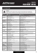
Page 15: ...CB Wire does not feed Feed roller rotates 1 Pressure roller improperly adjusted 2 Dirt copper dust etc have collected in torch liner 3 Gas cup nozzle or tip defective 4 Deformed wire 1 Adjust tension...

Page 16: ...l 11 Nut M8 45 Castor Wheel 12 Fan 46 Thermal Switch 13 Inner Panel 47 Axle Bracket 14 Resistance 48 Pin 15 Relay 49 Washer 16 Axle 50 Wheel 17 Bolt M8 x 25mm 51 Axle 18 Nut M10 52 Handle 19 Plastic K...

Page 17: ...17 USER MANUAL JEFMIG185 A JEFMIG210 A 185A MIG WELDER 230V 50Hz 210A MIG WELDER 230V 50Hz www jeffersontools com...

Page 18: ...the need to provide proof of purchase should a warranty claim be necessary Warranty Repair Should Jefferson confirm the existence of any defect covered by this warranty the defect will be corrected b...

Page 19: ...fective and in need of repair and any repairs needed are covered by the warranty policy In order to qualify for warranty cover all equipment presented must have been used serviced and maintained as in...

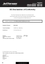
Page 20: ...following Directives EN 60974 1 as amended Arc welding equipment Welding power sources Equipment Category MIG Welder Product Name Model JEFMIG185 A JEFMIG210 A Notified Body TUV Product Service Ltd S...

Page 21: ...21 USER MANUAL JEFMIG185 A JEFMIG210 A 185A MIG WELDER 230V 50Hz 210A MIG WELDER 230V 50Hz www jeffersontools com Notes...

Page 22: ...22 USER MANUAL JEFMIG185 A JEFMIG210 A 185A MIG WELDER 230V 50Hz 210A MIG WELDER 230V 50Hz www jeffersontools com Notes...

Page 23: ...23 USER MANUAL JEFMIG185 A JEFMIG210 A 185A MIG WELDER 230V 50Hz 210A MIG WELDER 230V 50Hz www jeffersontools com...

Page 24: ...Herons Way Chester Business Park Chester United Kingdom CH4 9QR Tel 44 0 1244 646 048 Email sales jeffersontools com Before attempting to use this product please read all the safety precautions and o...

Reviews: