background image

13

USER MANUAL

JEFMIG185-A – JEFMIG210-A 

185A MIG WELDER - 230V 50Hz

210A MIG WELDER - 230V 50Hz

www.jeffersontools.com

PRECAUTIONS

• 

Ensure that there is free air circulating around the outer casing of the 
welder, and that the air vents are unobstructed.

• 

Welding arc can seriously damage your eyes. Both the operator and 
spectators must always use a suitable welding face shield or helmet, with 
suitable filter lenses for the welding processes. 

• 

Suitable Personal Protection Equipment (PPE) including gloves and 
working clothes should be worn at all times.

• 

Always check and ensure that the pressure regulator and gauges (if fitted) are working correctly before use. 

• 

Regulators are designed to be used with specific gases, it is important that you use the correct regulator for the gas required.

• 

Do not lubricate the regulator. 

• 

Inspect gas hoses, cables and clamps before use to ensure they are in good condition.

• 

Remove all flammable materials from the working environment before use.

• 

Keep a fire extinguisher nearby at all times. The extinguisher should be Dry Powder or CO

2

 type. 

• 

Do not remove any of the casing panels for repair or maintenance unless the machine is disconnected from the supply, 
and never use the machine with any of the panels removed. All repairs should be carried out by qualified engineers using 
Jefferson approved parts. Contact your nearest Jefferson Dealer for details. 

• 

Never use or store this equipment in a wet or damp environment and do not expose the equipment to rain during use.

• 

The MIG welding process uses an inert gas to protect the weld pool. It is important to ensure the appropriate gas is being used. 

• 

Never use an unknown or unidentifiable gas supply or gas from a damaged or unmarked cylinder.

• 

Do not lift or move a gas cylinder by holding he cylinder by the valve.

• 

Do not expose the cylinder to a heat source or sparks while in storage or in use.

• 

Stop welding immediately if any static / electric shocks are felt or detected. Do not attempt to weld using the equipment until 
the source of the fault is identified and repaired. 

• 

Do not point the MIG torch at anyone when in use.

• 

Do not touch the MIG torch nozzle until the welder is switched 

OFF

 and the nozzle has been allowed to cool off.

• 

Never connect, disconnect, or attempt to service the MIG torch, until the machine is switched 

OFF

 and disconnected from 

the mains power supply.

• 

Never allow the equipment cables to become wrapped around the operator or any bystanders in the working environment. 

8. Operation Guidelines

Before welding:

• 

Read and understand the safety rules section of this manual

• 

Ensure all flammable materials are removed the work area

• 

Ensure there is good ventilation around the welding unit and the working environment

• 

Enure you have a fire-extinguisher in the vicinity of the working environment and that it is ready for use in the event of fire

• 

Wear appropriate protective clothing and insulated leather gloves (check with your nearest Jefferson Dealer for advice) 

Step 1:  

Connect work clamp onto metal to be welded, or to the metal workbench where the object is mounted and electrically 
connected.

Step 2: 

Before plugging in, adjust the amperage and wire feed speed according to material type and thickness, and the wire size.

Step 3: 

Check the power switch is in the 

OFF

 position, and then plug the power cable into the electrical outlet.

Step 4:  

While holding the torch with the wire and tip clearly out of the way of any grounded objects, turn the power switch to  

ON 

position.

Step 5: 

Orient yourself on the area to be welded, and then place the face shield over your eyes. 

Step 6:

 Press (and hold) the torch button and stroke the area to be welded 

with the electrode wire to ignite the arc.

Step 7: 

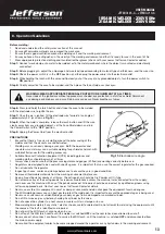
Once the arc is ignited, tilt the electrode wire forward at an angle of 

approximately 35° (as shown in 

Fig.15

).

Step 8: 

When the weld is complete, release the torch button and lift the wire 

clearly away from any grounded object, set the Face Shield down and turn 
the Power Switch to the “

OFF

” position. 

Step 9: 

Unplug the Power Cord from the electrical outlet.

WARNING: WEAR APPROPRIATE PERSONAL PROTECTION EQUIPMENT AT ALL TIMES


Never look at the ignited arc without approved, arc shaded, eye protection in a full-face shield. Permanent 
eye damage or blindness can occur. Skin burns can occur. Never breathe arc fumes.

Fig.15

 Electrode wire angle

Summary of Contents for JEFMIG185-A

Page 1: ...User Manual v 1 1 JEFMIG185 A JEFMIG210 A...

Page 2: ......

Page 3: ...he product and prior to any maintenance tasks By following all the general safety instructions contained in this manual you will help to ensure operator safety and extend the potential lifespan of the...

Page 4: ...rced Air Torch Euro Non Live BINZEL ERGO 15 2 2 Introduction Specification 3 1 ELECTRICAL SAFETY WARNING It is the user s responsibility to read understand and comply with the following You must check...

Page 5: ...able extension reel is used it should be fully unwound before connection A cable reel with an RCD fitted is recommended since any product which is plugged into the cable reel will be protected The cro...

Page 6: ...oes Turn voltage switch to OFF when not in use DO NOT operate the welder if it or its cables are damaged and DO NOT attempt to fit any unapproved torch or other parts to the welder unit DO NOT get wel...

Page 7: ...hten yet 4 2 2 Slide the handle tube 2 into the socket in the mounting and push fully home 4 2 3 Slide the socket on the right hand handle mounting 3 over the free end of the handle tube and rotate th...

Page 8: ...r Failure to do this could cause the wire to slip and or bind 4 7 1 Unscrew the locking knob from the end of the spool holder see fig 7 and remove the spacer Slide the reel of wire onto the spool hold...

Page 9: ...CHANGING THE DRIVE ROLLER See fig 12 Ensure that the wire diameter used is matched by the correct groove size in the drive wheel and the correct tip size on the torch as well as the correct torch lin...

Page 10: ...you to choose the correct voltage level for the thickness and type of metal being welded 5 3 Wire speed control knob Used to control the wire speed turn clockwise to increase the wire speed or counte...

Page 11: ...ng with a continuous flow of welding wire 4 Symbol for Single phase AC supply 5 Rating of internal protection provided by casing 6 Output U0 Rated minimum and maximum no load voltage I2 U2 Current and...

Page 12: ...lded a Best connection is obtained by grinding clean the point of contact on the workpiece before connecting the earth clamp b The weld area must also be free of paint rust grease etc c When welding a...

Page 13: ...nt the MIG torch at anyone when in use Do not touch the MIG torch nozzle until the welder is switched OFF and the nozzle has been allowed to cool off Never connect disconnect or attempt to service the...

Page 14: ...on 4 8 for removal and replacement 9 5 GAS CUP The gas cup must also be kept clean and free from spatter Build up of spatter inside the gas cup can cause a short circuit at the contact tip which will...

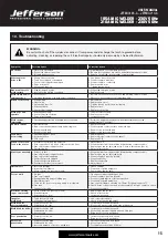
Page 15: ...CB Wire does not feed Feed roller rotates 1 Pressure roller improperly adjusted 2 Dirt copper dust etc have collected in torch liner 3 Gas cup nozzle or tip defective 4 Deformed wire 1 Adjust tension...

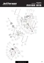
Page 16: ...l 11 Nut M8 45 Castor Wheel 12 Fan 46 Thermal Switch 13 Inner Panel 47 Axle Bracket 14 Resistance 48 Pin 15 Relay 49 Washer 16 Axle 50 Wheel 17 Bolt M8 x 25mm 51 Axle 18 Nut M10 52 Handle 19 Plastic K...

Page 17: ...17 USER MANUAL JEFMIG185 A JEFMIG210 A 185A MIG WELDER 230V 50Hz 210A MIG WELDER 230V 50Hz www jeffersontools com...

Page 18: ...the need to provide proof of purchase should a warranty claim be necessary Warranty Repair Should Jefferson confirm the existence of any defect covered by this warranty the defect will be corrected b...

Page 19: ...fective and in need of repair and any repairs needed are covered by the warranty policy In order to qualify for warranty cover all equipment presented must have been used serviced and maintained as in...

Page 20: ...following Directives EN 60974 1 as amended Arc welding equipment Welding power sources Equipment Category MIG Welder Product Name Model JEFMIG185 A JEFMIG210 A Notified Body TUV Product Service Ltd S...

Page 21: ...21 USER MANUAL JEFMIG185 A JEFMIG210 A 185A MIG WELDER 230V 50Hz 210A MIG WELDER 230V 50Hz www jeffersontools com Notes...

Page 22: ...22 USER MANUAL JEFMIG185 A JEFMIG210 A 185A MIG WELDER 230V 50Hz 210A MIG WELDER 230V 50Hz www jeffersontools com Notes...

Page 23: ...23 USER MANUAL JEFMIG185 A JEFMIG210 A 185A MIG WELDER 230V 50Hz 210A MIG WELDER 230V 50Hz www jeffersontools com...

Page 24: ...Herons Way Chester Business Park Chester United Kingdom CH4 9QR Tel 44 0 1244 646 048 Email sales jeffersontools com Before attempting to use this product please read all the safety precautions and o...

Reviews: