background image

7

USER MANUAL

JEFMIG185-A – JEFMIG210-A 

185A MIG WELDER - 230V 50Hz

210A MIG WELDER - 230V 50Hz

www.jeffersontools.com

4.1  

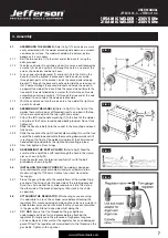
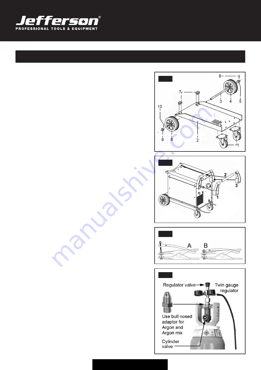
 ASSEMBLING THE WHEELS: 

(Refer to fig.1) The wheels are more 

easily assembled with the welder placed upside down on a smooth 
non-abrasive surface. The welder should be turned over by two 
people as it is very heavy.

4.1.1  

 Bolt the two castors (1) to the front end of the base (2) using the 
bolts provided.

4.1.2  

 Take the solid axle (3) and slide a wheel (4) over one end followed by 
a washer (5). Insert a split pin (6) through the hole in one end of the 
axle as shown below and bend it over.

4.1.3  

 Take an axle retaining bracket (7) and insert it into the slots in the 
base (2). Hold the bracket in place and slide the axle assembly 
through both parts of the bracket. Insert the second axle retaining 
bracket (7) through the base and continue to slide the axle across so 
that it passes through the second bracket and holds the wheel (4) 
up against the side of the base. Slide the second wheel (8) onto the 
free end of the axle followed by a washer (9). Retain the entire axle 
assembly by passing a split pin (10) through the free end of the axle 
and bend it over to retain the whole axle assembly.

4.1.4  

 With the assistance of another person turn the welder the right way 
up onto its wheels.

4.2  

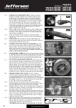
 ASSEMBLING THE HANDLE:

 (Refer to fig.2) On the front of the 

welder there are two pairs of threaded inserts, one pair in the top 
left corner and one pair in the top right hand corner..

4.2.1    Attach the left hand handle mounting (1) to the front of the welder 

using two of the 25mm round headed bolts provided. Do not fully 
tighten yet.

4.2.2    Slide the handle tube (2) into the socket in the mounting and push 

fully home.

4.2.3  

 Slide the socket on the right hand handle mounting (3) over the free 
end of the handle tube and rotate the mounting downwards until it 
is resting on the front of the welder. Using two of the 25mm round 
headed bolts provided to fix the right hand mounting in place.

4.2.4  

Now fully tighten all four fixings.

4.3  

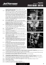
 ASSEMBLING THE EARTH CLAMP:

 (Refer to fig.3) Feed the 

eyelet on the end of the earth lead through the hole in the clamp 
arm as shown in fig.3A. 

4.3.1  

 Drop the eyelet over the terminal and firmly fix with the bolt 
provided as shown in fig.3B.

4.4  

 INSTALLING THE GAS CYLINDER.

 The welder is designed 

to accommodate small or medium sized gas cylinders up to a 
maximum height of 1000mm. Contact your local Gas dealer  
for supply.

4.4.1  

 Place the gas cylinder onto the rear platform of the welder. Drop 
one end of the fixing chain into one side of the retaining bracket. 
Draw the chain around the cylinder and place it into the slot on  
the other side of the bracket leaving as little slack in the chain  
as possible.

4.5  

 ATTACHING THE REGULATOR.

 Whichever gas you are using 

it is advisable to 'crack' the cylinder valve before attaching the 
regulator. This means opening and closing the valve very quickly in 
order to blow away any dust and dirt that may have accumulated 
in the gas outlet. Stand to one side whilst doing this.

4.5.1


 CO²  GAS.

 Ensure that the threads on the gas bottle are 

undamaged and free of oil and grease before attaching the 
regulator. (Oil or grease in the presence of high pressure gases 
can be explosive.) E Ensure that the regulator has an undamaged 
gasket fitted. The regulator will screw directly to the threads on the 
gas bottle. Tighten with a spanner.

4. Assembly

FIG. 1

FIG. 4

FIG. 2

FIG. 3

Summary of Contents for JEFMIG185-A

Page 1: ...User Manual v 1 1 JEFMIG185 A JEFMIG210 A...

Page 2: ......

Page 3: ...he product and prior to any maintenance tasks By following all the general safety instructions contained in this manual you will help to ensure operator safety and extend the potential lifespan of the...

Page 4: ...rced Air Torch Euro Non Live BINZEL ERGO 15 2 2 Introduction Specification 3 1 ELECTRICAL SAFETY WARNING It is the user s responsibility to read understand and comply with the following You must check...

Page 5: ...able extension reel is used it should be fully unwound before connection A cable reel with an RCD fitted is recommended since any product which is plugged into the cable reel will be protected The cro...

Page 6: ...oes Turn voltage switch to OFF when not in use DO NOT operate the welder if it or its cables are damaged and DO NOT attempt to fit any unapproved torch or other parts to the welder unit DO NOT get wel...

Page 7: ...hten yet 4 2 2 Slide the handle tube 2 into the socket in the mounting and push fully home 4 2 3 Slide the socket on the right hand handle mounting 3 over the free end of the handle tube and rotate th...

Page 8: ...r Failure to do this could cause the wire to slip and or bind 4 7 1 Unscrew the locking knob from the end of the spool holder see fig 7 and remove the spacer Slide the reel of wire onto the spool hold...

Page 9: ...CHANGING THE DRIVE ROLLER See fig 12 Ensure that the wire diameter used is matched by the correct groove size in the drive wheel and the correct tip size on the torch as well as the correct torch lin...

Page 10: ...you to choose the correct voltage level for the thickness and type of metal being welded 5 3 Wire speed control knob Used to control the wire speed turn clockwise to increase the wire speed or counte...

Page 11: ...ng with a continuous flow of welding wire 4 Symbol for Single phase AC supply 5 Rating of internal protection provided by casing 6 Output U0 Rated minimum and maximum no load voltage I2 U2 Current and...

Page 12: ...lded a Best connection is obtained by grinding clean the point of contact on the workpiece before connecting the earth clamp b The weld area must also be free of paint rust grease etc c When welding a...

Page 13: ...nt the MIG torch at anyone when in use Do not touch the MIG torch nozzle until the welder is switched OFF and the nozzle has been allowed to cool off Never connect disconnect or attempt to service the...

Page 14: ...on 4 8 for removal and replacement 9 5 GAS CUP The gas cup must also be kept clean and free from spatter Build up of spatter inside the gas cup can cause a short circuit at the contact tip which will...

Page 15: ...CB Wire does not feed Feed roller rotates 1 Pressure roller improperly adjusted 2 Dirt copper dust etc have collected in torch liner 3 Gas cup nozzle or tip defective 4 Deformed wire 1 Adjust tension...

Page 16: ...l 11 Nut M8 45 Castor Wheel 12 Fan 46 Thermal Switch 13 Inner Panel 47 Axle Bracket 14 Resistance 48 Pin 15 Relay 49 Washer 16 Axle 50 Wheel 17 Bolt M8 x 25mm 51 Axle 18 Nut M10 52 Handle 19 Plastic K...

Page 17: ...17 USER MANUAL JEFMIG185 A JEFMIG210 A 185A MIG WELDER 230V 50Hz 210A MIG WELDER 230V 50Hz www jeffersontools com...

Page 18: ...the need to provide proof of purchase should a warranty claim be necessary Warranty Repair Should Jefferson confirm the existence of any defect covered by this warranty the defect will be corrected b...

Page 19: ...fective and in need of repair and any repairs needed are covered by the warranty policy In order to qualify for warranty cover all equipment presented must have been used serviced and maintained as in...

Page 20: ...following Directives EN 60974 1 as amended Arc welding equipment Welding power sources Equipment Category MIG Welder Product Name Model JEFMIG185 A JEFMIG210 A Notified Body TUV Product Service Ltd S...

Page 21: ...21 USER MANUAL JEFMIG185 A JEFMIG210 A 185A MIG WELDER 230V 50Hz 210A MIG WELDER 230V 50Hz www jeffersontools com Notes...

Page 22: ...22 USER MANUAL JEFMIG185 A JEFMIG210 A 185A MIG WELDER 230V 50Hz 210A MIG WELDER 230V 50Hz www jeffersontools com Notes...

Page 23: ...23 USER MANUAL JEFMIG185 A JEFMIG210 A 185A MIG WELDER 230V 50Hz 210A MIG WELDER 230V 50Hz www jeffersontools com...

Page 24: ...Herons Way Chester Business Park Chester United Kingdom CH4 9QR Tel 44 0 1244 646 048 Email sales jeffersontools com Before attempting to use this product please read all the safety precautions and o...

Reviews: