www.jeffersontools.com
User Manual
v.1.1
JEFPDB0350
7. ASSEMBLY
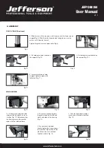
CHUCK & ARBOR
Fig.17
Fig.18
1. Before any assembly, ensure the
chuck jaws are wound all the way up
(inside the chuck) to prevent them
from damage (Fig. 17).
Fig.19
Fig.20
3. Fit the tapered arbor end into the chuck by
hand, using reasonable fore (Fig. 19).
4. The arbor can then be
inserted into the quill,
twisting the arbor as you
insert, aligning the tang
into the slot. It should fit
in with little resistance
(Fig. 20).
Fig.21
5. Once it is located a firm tap
on the underside of the chuck
with a soft hammer is required
to secure it. The chuck & arbor
are installed correctly if they
cannot be pulley out with hand
force (Fig. 21).
2. Tighten Philip’s head screws
of the chuck guard to quill shaft
(Fig. 18).
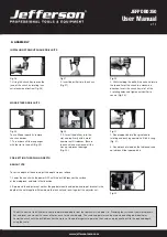
TABLE HEIGHT & ADJUSTMENT
Fig.22
1. Loosen the table
support lock (Fig. 22).
Fig.23
2. Rotate the table
adjustment handle to set
the desired table height
and tighten the table rock
to secure the table in
position (Fig. 23).
TABLE BEVEL ADJUSTMENT
Fig.24
1. The bevel angel is
adjusted by loosening
the bolt that is located
underneath table support
with a spanner (Fig. 24).
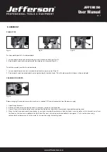
Fig.25
2. After tilting the
working table (Fig. 25)
to appropriate position,
re-tighten the bolt to
secure its position.
When the table is angled/tilted,
ensure the workpiece is clamped
to the table.
CAUTION:

