www.jeffersontools.com
User Manual
v.1.1
JEFPDB0350
9. ASSEMBLY
FLOOR TYPE
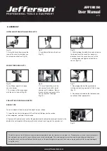
Fig.33
Fig.34
To stop spindle (and bit) at a desired depth:
1. Loosen depth stop lock knob by turning in an anti-clockwise direction (Fig. 33).
2. Rotate depth scale to the desired depth, then tighten half wing bolt (Fig. 34).
To hold the spindle (and bit) at a desired depth:
1. Loosen depth stop lock knob, turn feed wheel handle to lowest point (Fig.35).
2. Rotate depth scale to desired depth and re-tighten depth stop lock knob. This will hold assembly stationery at desired depth.
Fig.35
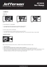
CHANGING THE SPEED
Fig.36
Before changing the speeds, ensure the machine is switched OFF, and disconnected from the power supply.
1. Open the pulley cover.
2. Slacken off the belt tension locking knob, to relieve any tension on the drive belt.
3. Consult the chart inside the pulley cover, and position the belt on the pulley’s according to the spindle speed required.
4. When the belt has been correctly positioned, re-tension by levering the motor away from the head. Lever the motor, with its bracket, away from
the head, so that tension is applied to the Fig.36 belt. Tension is correct when the belt deflects by approx. ½”at its centre, when using
reasonable thumb pressure. Lock the motor in this position using the locking knob.

