background image

www.jeffersontools.com

User Manual 

v.1.1

JEFPDB0350

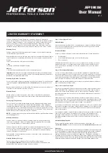
Jefferson Professional Tools & Equipment, or hereafter “Jefferson” warrants its 
customers that its products will be free of defects in workmanship or material. Jefferson 
shall, upon suitable notification, correct any defects, by repair or replacement, of any 
parts or components of this product that are determined by Jefferson to be faulty 
or defective.  This warranty is void if the equipment has been subjected to improper 
installation, storage, alteration, abnormal operations, improper care, service or repair. 

Warranty Period

Jefferson will assume both the parts and labour expense of correcting defects during 
the stated warranty periods below. 

All warranty periods start from the date of purchase from an authorised Jefferson dealer. 
If proof of purchase is unavailable from the end user, then the date of purchase will be 
deemed 
to be 3 months after the initial sale to the distributor.  

1 Year


• 

Jefferson 350W Bench Drill [JEFPDB0350]. 

90 Days 

•  All replacement parts purchased outside of the warranty period 

Important: 

All parts used in the repair or replacement of warranty covered equipment 

will be subject to a minimum of 90 days cover or the remaining duration of the warranty 
period from the original date of purchase

.    

Warranty Registration / Activation

You can register and activate your warranty by visiting the Jefferson Tools website using 
the following address: 

www.jeffersontools.com/warranty

 and completing the online 

form. 

Online warranty registration is recommended as it eliminates the need to provide proof 
of purchase should a warranty claim be necessary. 

Warranty Repair

 
Should Jefferson confirm the existence of any defect covered by this warranty the 
defect will be corrected by repair or replacement at an authorized Jefferson dealer or 
repair centre. 

Packaging & Freight Costs

 
The customer is responsible for the packaging of the equipment and making it ready 
for collection. Jefferson will arrange collection and transportation of any equipment 
returned under warranty. Upon inspection of the equipment, if no defect can be found 
or the equipment is not covered under the terms of the Jefferson warranty, the customer 
will be liable for any labour and return transportation costs incurred. These costs will be 
agreed with the customer before the machine is returned.   

NOTE: *

 Jefferson reserve the right to void any warranty for damages identified as being 

caused through misuse * 


Warranty Limitations

Jefferson will not accept responsibility or liability for repairs made by unauthorised 
technicians or engineers.  Jefferson’s liability under this warranty will not exceed the 
cost of correcting the defect of the Jefferson products. 

Jefferson will not be liable for incidental or consequential damages (such as loss of 
business or hire of substitute equipment etc.) caused by the defect or the time involved 
to correct the defect. This written warranty is the only express warranty provided by 
Jefferson with respect to its products.  
 
Any warranties of merchantability are limited to the duration of this limited warranty for 
the equipment involved.  

Claiming Warranty Coverage 

The end user must contact Jefferson Professional Tools & Equipment: 

(Tel: +44 (0) 1244 646 048)

 or their nearest authorised Jefferson dealer where final 

determination of the warranty coverage can be ascertained. 

Step 1 - Reporting the Defect 

Online Method:

Visit our website www.jeffersontools.com/warranty and complete the Warranty Returns 
form. You can complete the form online and submit it to us directly or download the 
form to print out and return by post.

Telephone Method: 

Contact your Jefferson dealer or sales representative with the following information:

• 

Model number 

• 

Serial number (usually located on the specification plate) 

• 

Date of purchase 

A Warranty Returns form will be sent to you for completion and return by post or fax, 
together with details of your nearest authorised Jefferson repair centre. On receipt 
of this form Jefferson will arrange to collect the equipment from you at the earliest 
convenience.  

Step 2 - Returning the Equipment 


It is the customer’s responsibility to ensure that the equipment is appropriately and 
securely packaged for collection, together with a copy of the original proof of purchase. 
Please note that Jefferson cannot assume any responsibility for any damage incurred 
to equipment during transit. Any claims against a third party courier will be dealt with 
under the terms & conditions of their road haulage association directives.   

NOTE:


Jefferson will be unable to collect or process any warranty requests without a 

copy of the original proof of purchase. 

Step 3 - Assessment and Repair    

On receipt, the equipment will be assessed by an authorised Jefferson engineer and it 
will be determined if the equipment is defective and in need of repair and any repairs 
needed are covered by the warranty policy. In order to qualify for warranty cover all 
equipment presented must have been used, serviced and maintained as instructed in 
the user manual. 

Where repair is not covered by the warranty a quotation for repair, labour costs and 
return delivery will be sent to the customer (normally within 7 working days). Note: If the 
repair quotation is not accepted Jefferson Professional Tools & Equipment will invoice 1 
hour labour time at £30 per hour plus return carriage costs (plus VAT).   

In cases where no fault can be found with the equipment, or, if incorrect operation of the 
equipment is identified as the cause of the problem, a minimum of 1 hour labour at £30 
per hour plus carriage costs will be required before the equipment will be despatched 
back to the customer. 

Any equipment repaired or replaced under warranty will normally be ready for shipment 
back to the customer within 7 working days upon receipt of the equipment at an 
authorised Jefferson Repair centre (subject to part availability). Where parts are not 
immediately available Jefferson will contact you with a revised date for completion of 
the repair.  

General Warranty Enquiries 

For any further information relating to Jefferson warranty cover please call: 

 +44 (0) 1244 646 048

 or send your enquiry via email to 

warranty@jeffersontools.com

Disclaimer: 

The information in this document is to the best of our knowledge true and accurate, but 
all recommendations or suggestions are made without guarantee. Since the conditions 
of use are beyond their control, Jefferson Tools® disclaim any liability for loss or 
damage suffered from the use of this data or suggestions. Furthermore, no liability is 
accepted if use of any product in accordance with this data or suggestions infringes any 
patent. Jefferson Tools® reserve the right to change product specifications and warranty 
statements without further notification. All images are for illustration purposes only.

LIMITED WARRANTY STATEMENT

Summary of Contents for JEFPDB0350

Page 1: ...table allows for mounting clamps and vises for effective work holding Fitted with a table height adjustment control Supplied with a telescopic chuck guard and a front mounted NVR switch for added convenience and safety Drilling capacity Ø13mm Motor power 350W Chuck capacity 1 5 13mm Spindle Taper B16 Speeds 50Hz 620 2620 RPM Swing 210mm Spindle travel 50mm Column diameter Ø46mm Table size 160 x 16...

Page 2: ......

Page 3: ...on 8 Exploded diagram 9 Parts list 10 Troubleshooting 11 Declaration of conformity 12 Warranty statement 1 4 6 7 8 8 13 14 15 16 17 18 CONTENT Please read all safety warnings and all instructions Failure to follow the warnings and instructions may result in electric shock fire and or serious injury Store this instruction manual in a safe place for future reference WARNING ...

Page 4: ...arf by wearing approved safety goggles or a face shield These are some of the more common hazards and preventions however always find out what hazards are associated with the machine work process and wear the most suitable protective equipment available 1 11 Do not breathe contaminated air If the work creates dust or fumes connect the machine if possible to an extraction system either locally or r...

Page 5: ...e or combustible materials LOCATION 1 29 Posture Ensure when mounting the machine that the chosen location does not lead to unhealthy posture or repetitive strain during normal operation 1 30 Lighting Adequate lighting must be provided to ensure no operations are light impaired possibly leading to injury 1 31 Reach Do not reach over or around the machine at any time UNEXPECTED START UP 1 32 Remove...

Page 6: ...h cover panels removed 2 10 Have your tool repaired by a qualified person This tool complies with the relevant safety rules Repairs should only be carried out by qualified persons using original spare parts otherwise this may result in considerable danger to the user 2 11 NEVER use this product for any other purpose than that described in this booklet 2 12 NEVER abuse the power cable by yanking the ...

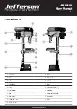
Page 7: ...19 1 Pulley cover 11 Base 2 Motor 12 Main housing 3 Switch 13 Column 4 Chuck guard 14 Bolts 5 Chuck 15 Depth stop lock knob 6 Feed handle 16 Table lock 7 Table 17 Table adjustment handle 8 Table holder 18 Rack collar 9 Belt tension lock knob 19 Rack 10 Column support 12 16 7 18 13 10 11 14 6 17 ...

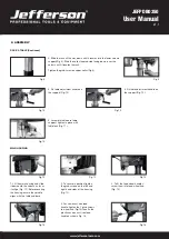
Page 8: ...terials in the reach of children 5 4 If any of the packaging is to be thrown away make sure they are disposed of correctly according to local regulations 5 ASSEMBLY BASE COLUMN Select the base Fig 1 and align the column support over the large hole Fig 2 Align the holes in the column support with those in the base and secure in place using the bolts and washers Using a spanner securely lighten all ...

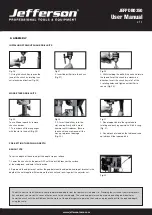
Page 9: ... on the support Fig 10 Fig 10 5 Assemble table onto table support tighten in place with table lock Fig 11 1 Lift the main housing and slide it down onto the column as far as it will go Fig 12 Before securing the housing ensure the spindle aligns with the table and base 3 To fit the feed wheel handles screw them into feed wheel hub Fig 14 2 To secure in position tighten the grub screws on the left a...

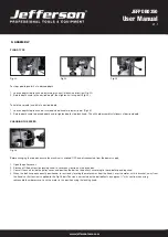
Page 10: ...er is required to secure it The chuck arbor are installed correctly if they cannot be pulley out with hand force Fig 21 2 Tighten Philip s head screws of the chuck guard to quill shaft Fig 18 TABLE HEIGHT ADJUSTMENT Fig 22 1 Loosen the table support lock Fig 22 Fig 23 2 Rotate the table adjustment handle to set the desired table height and tighten the table rock to secure the table in position Fig...

Page 11: ...Insert the drill key into the slot and tap firmly with a metal hammer until it releases Ensure the chuck jaws are wound all the way up to prevent damage Fig 30 PRE SETTING THE DRILLING DEPTH BENCH TYPE To set the depth of the hole adjust the depth stop as follows 1 Lower the chuck with the power OFF until the drill bit touches the surface of the workpiece and hold in that position 2 Spin down the a...

Page 12: ...red depth Fig 35 CHANGING THE SPEED Fig 36 Before changing the speeds ensure the machine is switched OFF and disconnected from the power supply 1 Open the pulley cover 2 Slacken off the belt tension locking knob to relieve any tension on the drive belt 3 Consult the chart inside the pulley cover and position the belt on the pulley s according to the spindle speed required 4 When the belt has been ...

Page 13: ...ck with the chuck key by turning in an anti clockwise direction and insert the selected drill bit into the as far as it will go 3 Insert the chuck key into 1 of the 3 locating holes and tighten until drill bit is secure 4 Select your drilling depth and secure the depth stop lock knob in position 5 Adjust the table to your desired position 6 Slowly rotate the feed wheel handles to bring the drill b...

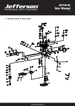
Page 14: ...www jeffersontools com User Manual v 1 1 JEFPDB0350 11 EXPLODED DIAGRAM OF BENCH PRESS ...

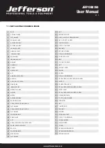
Page 15: ... CIRCLIP FOR BEARING 18 HOUSING 57 CROSS RECESS HEAD TAPPING SCREW 19 HEX SOC SET SCREW 58 SWITCH 20 WING KNOB 59 CALIBRATION LABEL 21 MOTOR SPRING 60 CROSS RECESSED PAN HEAD SCREW 22 MOTOR PUSH ROB 61 SWITCH BOX 23 WASHER 62 CROSS RECESSED PAN HEAD SCREW 24 MOTOR 63 GROUNDED PARTS 25 OUTSIDE HEX BOLT 64 TOOTH LOCK WASHER 26 DAMPING WASHER 65 INDICATOR 27 CROSS RECESS PAN HD SCREW 66 NUT 28 FLAT W...

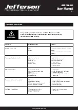
Page 16: ...le 3 Blunt bit 4 Feeding too slow 5 Not lubricated 1 Change speed 2 Retract bit frequency to clear swaft 3 Sharpen or replace bit 4 Feed fast enough to allow drill to cut 5 Lubricate bit Excessive drill run out or wobble 1 Bent bit 2 Worn spindle bearings 3 Bit not properly installed in chuck 4 Chuck not properly installed 1 Use a straight bit 2 Return to an authorised service agent 3 Install bit ...

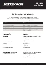
Page 17: ...amended Restriction of Hazardous Substance Directive RoHS Equipment Category Bench Drill Pillar Drill Drill Press Product Name Model JEFPDB0350 Notified Body TÜV SÜD Product Service GmbH Zertifizierstellen Ridlerstraße 65 80339 MÜNCHEN Country Germany http www tuev sued de ps Notified Body Number 0123 Signed by Stephen McIntyre Position in the company Operations Director Date 31 January 2018 Name ...

Page 18: ...warranty coverage can be ascertained Step 1 Reporting the Defect Online Method Visit our website www jeffersontools com warranty and complete the Warranty Returns form You can complete the form online and submit it to us directly or download the form to print out and return by post Telephone Method Contact your Jefferson dealer or sales representative with the following information Model number Se...

Page 19: ...www jeffersontools com User Manual v 1 1 JEFPDB0350 NOTES ...

Page 20: ...www jeffersontools com User Manual v 1 1 JEFPDB0350 JEFPDB0350 350W BENCH DRILL ...

Reviews: