background image

www.jeffersontools.com

User Manual 

v.1.1

JEFPDB0350

1. SAFETY

GENERAL SAFETY INSTRUCTIONS FOR POWER TOOL USE 

When using any type of power tool there are steps that should be taken to make sure that you, as the user, remain safe. 
Common sense and a respect for the tool will help reduce the risk of injury. 

1.1   Read the instruction manual fully. Do not attempt any operation until you have read and understood this manual. Most important you must  
 

know how to safely start and stop this machine, especially in an emergency. 

1.2   Keep the work area tidy and clean. Attempting to clear clutter from around the machine during use will reduce your concentration. Mess on  
 

the floor creates a trip hazard. Any liquid spilt on the floor could result in you slipping. 

1.3  Find a suitable location. If the machine is bench mounted; the location should provide good natural light or artificial lighting as a replacement.  
 

Avoid damp and dust locations as it will have a negative effect on the machine’s performance. If the machine is portable; do not expose the  


tool to rain. In all cases do not operate power tools near any flammable materials. 

1.4  Beware of electric shock. Avoid contact with earthed surfaces; because they can conduct electricity if there is an electrical fault with the  
 

power tool. Always protect the power cable and route it away from danger. 

1.5  Keep bystanders away. Children, onlookers and passers by must be restricted from entering the work area for their own protection. The  
 

barrier must extend a suitable distance from the tool user. 

1.6  Unplug and house all power tools that are not in use. A power tool should never be left unattended while connected to the power supply.  
 

They must be housed in a suitable location, away locked up and from children. 

1.7  Do not overload or misuse the tool. All tools are designed for a purpose and are limited to what they are capable of doing. Do not attempt to  
 

use a power tool (or adapt it in any way) for an application it is not designed for. Select a tool appropriate for the size of the job. Overloading  


a tool will result in tool failure and user injury: This covers the use of accessories. 

1.8  Dress properly. Loose clothing, long hair and jewellery are all dangerous because they can become entangled in moving machinery: This can  
 

also result in parts of body being pulled into the machine. 

1.9  Clothing should be close fitted, with any long hair tied back, jewellery and neck ties removed. 
 

Footwear must be fully enclosed and have a nonslip sole.

1.10  Wear personal protective equipment (PPE). Dust, noise, vibration and swarf can all be dangerous if not suitably protected against. If the work
 

involving the power tool creates dust or fumes; wear a dust mask. Vibration to the hand, caused by operating some tools for longer periods  


must be protected against. Wear vibration reducing gloves and allow long breaks between uses. Protect against dust and swarf by wearing  


approved safety goggles or a face shield. These are some of the more common hazards and preventions; however, always find out what  


hazards are associated with the machine/work process and wear the most suitable protective equipment available. 

1.11  Do not breathe contaminated air. If the work creates dust or fumes; connect the machine (if possible) to an extraction system either locally or  
 

remotely. Working outdoors can also help if possible. 

1.12  Move the machine as instructed. If the machine is hand held, do not carry it by the power supply cable. If the product is heavy; employ a  
 

second or third person to help move it safely or use a mechanical device. Always refer to the instructions for the correct method. 

1.13  Do not overreach. Extending your body too far can result in a loss of balance and you falling. This could be from a height or onto a machine  
 

and will result in injury. 

1.14  Maintain your tools correctly. A well maintained tool will do the job safely. Replace any damaged or missing parts immediately with original  
 

parts from the manufacturer. As applicable; keep blades sharp; moving parts clean, oiled or greased; handles clean; 


and emergency devices working. 

1.15  Wait for the machine to stop. Unless the machine is fitted with a safety brake; some parts may continue to move due to momentum. Wait for  
 

all parts to stop; then unplug it from the power supply before making any adjustments, carrying out maintenance operations 


or just finishing using the tool. 

1.16  Remove and check setting tools. Some machinery requires the use of additional tools or keys to set, load or adjust the power tool. Before  
 

starting the power tool always check to make certain they have been removed and are safely away from the machine. 

1.17  Prevent unintentional starting. Before plugging any machine in to the power supply, make sure the switch is in the OFF position. If the    
 

machine is portable; do not hold the machine near the switch and take care when putting the machine down; 


that nothing can operate the switch. 

1.18  Carefully select an extension lead. Some machines are not suitable for use with extension leads. If the tool is designed for use outdoors; use  
 

an extension lead also suitable for that environment. When using an extended lead, select one capable of handling the current (amps) drawn  


by the machine in use. Fully extend the lead regardless of the distance between the power supply and the tool. Excess current  


(amps) and a coiled extension lead will both cause the cable to heat up and can result in fire. 

1.19  Concentrate and stay alert. Distractions are likely to cause an accident. Never operate a power tool if you are under the influence of drugs  
 

(prescription or otherwise), including alcohol or if you are feeling tired. Being disorientated will result in an accident.

1.20  Have this tool repaired by a qualified person. This tool is designed to confirm to the relevant international and local standards and as such  
 

should be maintained and repaired by someone qualified; using only original parts supplied by the manufacturer: 


This will ensure the tool remains safe to use. 

Summary of Contents for JEFPDB0350

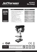
Page 1: ...table allows for mounting clamps and vises for effective work holding Fitted with a table height adjustment control Supplied with a telescopic chuck guard and a front mounted NVR switch for added convenience and safety Drilling capacity Ø13mm Motor power 350W Chuck capacity 1 5 13mm Spindle Taper B16 Speeds 50Hz 620 2620 RPM Swing 210mm Spindle travel 50mm Column diameter Ø46mm Table size 160 x 16...

Page 2: ......

Page 3: ...on 8 Exploded diagram 9 Parts list 10 Troubleshooting 11 Declaration of conformity 12 Warranty statement 1 4 6 7 8 8 13 14 15 16 17 18 CONTENT Please read all safety warnings and all instructions Failure to follow the warnings and instructions may result in electric shock fire and or serious injury Store this instruction manual in a safe place for future reference WARNING ...

Page 4: ...arf by wearing approved safety goggles or a face shield These are some of the more common hazards and preventions however always find out what hazards are associated with the machine work process and wear the most suitable protective equipment available 1 11 Do not breathe contaminated air If the work creates dust or fumes connect the machine if possible to an extraction system either locally or r...

Page 5: ...e or combustible materials LOCATION 1 29 Posture Ensure when mounting the machine that the chosen location does not lead to unhealthy posture or repetitive strain during normal operation 1 30 Lighting Adequate lighting must be provided to ensure no operations are light impaired possibly leading to injury 1 31 Reach Do not reach over or around the machine at any time UNEXPECTED START UP 1 32 Remove...

Page 6: ...h cover panels removed 2 10 Have your tool repaired by a qualified person This tool complies with the relevant safety rules Repairs should only be carried out by qualified persons using original spare parts otherwise this may result in considerable danger to the user 2 11 NEVER use this product for any other purpose than that described in this booklet 2 12 NEVER abuse the power cable by yanking the ...

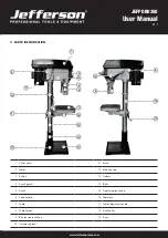
Page 7: ...19 1 Pulley cover 11 Base 2 Motor 12 Main housing 3 Switch 13 Column 4 Chuck guard 14 Bolts 5 Chuck 15 Depth stop lock knob 6 Feed handle 16 Table lock 7 Table 17 Table adjustment handle 8 Table holder 18 Rack collar 9 Belt tension lock knob 19 Rack 10 Column support 12 16 7 18 13 10 11 14 6 17 ...

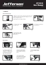
Page 8: ...terials in the reach of children 5 4 If any of the packaging is to be thrown away make sure they are disposed of correctly according to local regulations 5 ASSEMBLY BASE COLUMN Select the base Fig 1 and align the column support over the large hole Fig 2 Align the holes in the column support with those in the base and secure in place using the bolts and washers Using a spanner securely lighten all ...

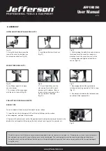
Page 9: ... on the support Fig 10 Fig 10 5 Assemble table onto table support tighten in place with table lock Fig 11 1 Lift the main housing and slide it down onto the column as far as it will go Fig 12 Before securing the housing ensure the spindle aligns with the table and base 3 To fit the feed wheel handles screw them into feed wheel hub Fig 14 2 To secure in position tighten the grub screws on the left a...

Page 10: ...er is required to secure it The chuck arbor are installed correctly if they cannot be pulley out with hand force Fig 21 2 Tighten Philip s head screws of the chuck guard to quill shaft Fig 18 TABLE HEIGHT ADJUSTMENT Fig 22 1 Loosen the table support lock Fig 22 Fig 23 2 Rotate the table adjustment handle to set the desired table height and tighten the table rock to secure the table in position Fig...

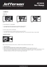
Page 11: ...Insert the drill key into the slot and tap firmly with a metal hammer until it releases Ensure the chuck jaws are wound all the way up to prevent damage Fig 30 PRE SETTING THE DRILLING DEPTH BENCH TYPE To set the depth of the hole adjust the depth stop as follows 1 Lower the chuck with the power OFF until the drill bit touches the surface of the workpiece and hold in that position 2 Spin down the a...

Page 12: ...red depth Fig 35 CHANGING THE SPEED Fig 36 Before changing the speeds ensure the machine is switched OFF and disconnected from the power supply 1 Open the pulley cover 2 Slacken off the belt tension locking knob to relieve any tension on the drive belt 3 Consult the chart inside the pulley cover and position the belt on the pulley s according to the spindle speed required 4 When the belt has been ...

Page 13: ...ck with the chuck key by turning in an anti clockwise direction and insert the selected drill bit into the as far as it will go 3 Insert the chuck key into 1 of the 3 locating holes and tighten until drill bit is secure 4 Select your drilling depth and secure the depth stop lock knob in position 5 Adjust the table to your desired position 6 Slowly rotate the feed wheel handles to bring the drill b...

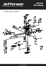
Page 14: ...www jeffersontools com User Manual v 1 1 JEFPDB0350 11 EXPLODED DIAGRAM OF BENCH PRESS ...

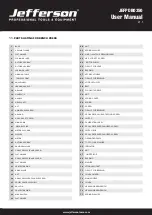
Page 15: ... CIRCLIP FOR BEARING 18 HOUSING 57 CROSS RECESS HEAD TAPPING SCREW 19 HEX SOC SET SCREW 58 SWITCH 20 WING KNOB 59 CALIBRATION LABEL 21 MOTOR SPRING 60 CROSS RECESSED PAN HEAD SCREW 22 MOTOR PUSH ROB 61 SWITCH BOX 23 WASHER 62 CROSS RECESSED PAN HEAD SCREW 24 MOTOR 63 GROUNDED PARTS 25 OUTSIDE HEX BOLT 64 TOOTH LOCK WASHER 26 DAMPING WASHER 65 INDICATOR 27 CROSS RECESS PAN HD SCREW 66 NUT 28 FLAT W...

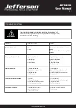
Page 16: ...le 3 Blunt bit 4 Feeding too slow 5 Not lubricated 1 Change speed 2 Retract bit frequency to clear swaft 3 Sharpen or replace bit 4 Feed fast enough to allow drill to cut 5 Lubricate bit Excessive drill run out or wobble 1 Bent bit 2 Worn spindle bearings 3 Bit not properly installed in chuck 4 Chuck not properly installed 1 Use a straight bit 2 Return to an authorised service agent 3 Install bit ...

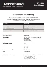
Page 17: ...amended Restriction of Hazardous Substance Directive RoHS Equipment Category Bench Drill Pillar Drill Drill Press Product Name Model JEFPDB0350 Notified Body TÜV SÜD Product Service GmbH Zertifizierstellen Ridlerstraße 65 80339 MÜNCHEN Country Germany http www tuev sued de ps Notified Body Number 0123 Signed by Stephen McIntyre Position in the company Operations Director Date 31 January 2018 Name ...

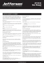
Page 18: ...warranty coverage can be ascertained Step 1 Reporting the Defect Online Method Visit our website www jeffersontools com warranty and complete the Warranty Returns form You can complete the form online and submit it to us directly or download the form to print out and return by post Telephone Method Contact your Jefferson dealer or sales representative with the following information Model number Se...

Page 19: ...www jeffersontools com User Manual v 1 1 JEFPDB0350 NOTES ...

Page 20: ...www jeffersontools com User Manual v 1 1 JEFPDB0350 JEFPDB0350 350W BENCH DRILL ...

Reviews: