background image

USER MANUAL

JEFC270T10B-230

270L

 BELT DRIVEN AIR COMPRESSOR 

 TANDEM 2x 3HP 

• 

10Bar 

www.jeffersontools.com

13

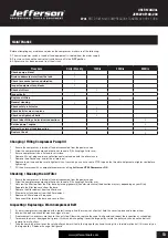
Before attempting any maintenance jobs on the compressor, make sure of the following:

1. 

The master power switch is tuned off and equipment is isolated from the mains supply.

2.

 Pressure switch and the control unit switches are all in the 

OFF

 position.

3.

 All pressure has been removed from the air tank.

Procedure 

Daily / Weekly

100Hrs

200Hrs

400Hrs

Check pump oil level 


Drain condensate water from the tank 


Check for unusual noise and vibration 


Inspect equipment for air leaks 


Check air filters 

Inspect belts

Replace air filters

General cleaning

Check safety relief valve 


Check belts for wear / replace 


Check and tighten all bolts 


Check tubes fittings & electrical connections 


Service pump / engine 

Internal & external tank inspection

Replace the oil

Changing / Filling Compressor Pump Oil

• 

Ensure the compressor is turned off and disconnected from the power source.

• 

Allow the compressor pump and other parts to cool off (if changing oil after use).

• 

Ensure compressor is on a flat and level surface.

• 

Remove fill cap / plug and place collection container underneath the oil drain cap.

• 

Remove the oil drain cap, and let the oil drain out.

• 

Replace the oil cap and be sure to tighten this nut securely (you can use some PTFE tape on the thread to help create a tighter seal before 
tightening). 

• 

Fill the oil reservoir with a compatible compressor oil (e.g 

Jefferson HT68 Compressor Oil

).  

Checking / Cleaning the Air Filter  

• 

Ensure the compressor is turned off and disconnected from the power source.

• 

Allow the compressor pump and other parts to cool off (if changing filter after use).

• 

Unscrew the filter top from the filter base by turning (generally) counter-clockwise (the direction may vary depending on your filter). 

• 

Separate the filter top cover from the base.

• 

Remove the filter element from the filter base.

• 

Blow out dust and debris from the filter element.

• 

Replace air filter element if required. 

• 

Reconnect filter top to the base and secure filter. 

Inspecting / Replacing a Worn Compressor Belt

• 

If your air compressor is equipped with a protective cage, find the screws or clips that hold the cover in place and remove them. 

• 

Inspect the belt and check for cracks or signs of wear.

• 

If replacement is necessary, move onto the next step. Otherwise, replace the cage / belt guard and repeat the inspection as scheduled.  

• 

To remove the worn / damaged belt, grasp it firmly and while pulling it over the large pulley, rotate the pulleys by hand and the belt will 
remove from all pulleys.

• 

Take the new belt, place it over the small pulley and work it onto the large pulley by hand-turning it in a forward motion until it is securely on 
the large pulley.  Replace the cage / belt guard.

  MAINTENANCE


Summary of Contents for TANDEM JEFC270T10B-230

Page 1: ...TANDEM 2x 3HP BELT DRIVEN User Manual v 2 1 JEFC270T10B 230...

Page 2: ...USER MANUAL JEFC270T10B 230 270L BELT DRIVEN AIR COMPRESSOR TANDEM 2x 3HP 10Bar www jeffersontools com 2...

Page 3: ...correct and safe use We recommend that this manual is read before any operation or before performing any kind of adjustment to the product and prior to any maintenance tasks By following all the gener...

Page 4: ...protection to the fly wheel and belt assembly Powder coated tank Welded tank fully compliant with the latest European manufacturing safety standards SPECIFICATIONS JEFC270T10B 230 Tank Capacity 270L...

Page 5: ...l from the head possibly leading to damage PLEASE NOTE THE FOLLOWING PHOTOGRAPHS INSTRUCTIONS ARE FOR REFERENCE ONLY AND MAY DIFFER FOR YOUR COMPRESSOR MODEL PLEASE CONTACT JEFFERSON TOOLS IF YOU NEED...

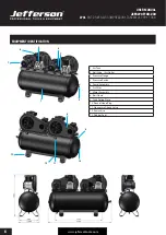
Page 6: ...ntools com 6 1 Air Tank 2 Ball Valve Air Outlet 3 Pressure Gauge 4 Pressure Switch 5 Pump Assembly 6 Air Filter 7 Motor Assembly 8 Belt Guard 9 Tank Rating Plate 10 Socket Head Plug 11 Non return Chec...

Page 7: ...gle in any direction is 15 degrees see Fig 8 Do not operate the compressor on inclines in excess of 15 degrees Serious damage to pump components may result from insufficient lubrication Never use the...

Page 8: ...this is often referred to as Portable Appliance Testing PAT PAT testing should be carried out regularly on this equipment by trained authorised personnel as required by the legislation The Health and...

Page 9: ...or air vent must be kept clean so that air can freely flow at all times Check for dust build up frequently and clean as required If the equipment appears to be operating unusually making strange noise...

Page 10: ...le and the shutter are not blocked by glue Teflon or similar materials that could bind the shutter or other functional components If the valve is replaced the compressed air contained in the system mu...

Page 11: ...pply to the compressor NOTE A secondary thermal cutout RESET button F is located in the control box see Fig 13 In the event of an overload cut out please allow 5 minutes for the machine to cool prior...

Page 12: ...USER MANUAL JEFC270T10B 230 270L BELT DRIVEN AIR COMPRESSOR TANDEM 2x 3HP 10Bar www jeffersontools com 12 ELECTRICAL CONNECTIONS CONTROL BOX WIRING DIAGRAM...

Page 13: ...nut securely you can use some PTFE tape on the thread to help create a tighter seal before tightening Fill the oil reservoir with a compatible compressor oil e g Jefferson HT68 Compressor Oil Checking...

Page 14: ...rised service agent There is a leak from the base of the pressure switch when the compressor is stopped The non return valve from the tank is leaking Disassemble and clean if necessary replace valve i...

Page 15: ...wise arise from inappropriate waste handling Please contact your local authority for further details of your nearest designated collection point Penalties may be applicable for incorrect disposal of t...

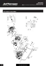
Page 16: ...USER MANUAL JEFC270T10B 230 270L BELT DRIVEN AIR COMPRESSOR TANDEM 2x 3HP 10Bar www jeffersontools com 16 PARTS DIAGRAM MAIN ASSEMBLY...

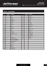
Page 17: ...1 Plug 28 1 Pressure Switch 11 1 Elbow 29 1 Saftey valve 12 2 Check Valve 30 1 Elbow 12 1 2 Bonnet 31 1 Pressure Gauge 12 2 2 O ring 32 1 Nipple 12 3 2 Spring 33 1 Quick coupler 12 4 2 Valve element 3...

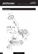
Page 18: ...USER MANUAL JEFC270T10B 230 270L BELT DRIVEN AIR COMPRESSOR TANDEM 2x 3HP 10Bar www jeffersontools com 18 PARTS DIAGRAM PUMP...

Page 19: ...pple 8 1 Front Support 32 2 Hex Bolt 9 2 Gasket 33 2 SP Washer 10 2 Bearing 34 1 Radiator 11 1 Crankshaft 35 1 Radiator Gasket 12 2 Connecting Rod 36 6 Hex Socket Bolt 13 4 Circlip 37 1 Air Filter Ass...

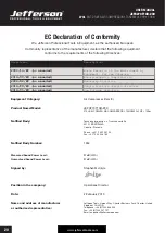
Page 20: ...ded Simple Pressure Vessels Directive 2014 35 EU as amended Low Voltage Directive Equipment Category Air Compressor Item 8 Product Name Model JEFC270T10B 230 270L BELT DRIVEN AIR COMPRESSOR TANDEM 2x...

Page 21: ...tence of any defect covered by this warranty the defect will be corrected by repair or replacement at an authorized Jefferson dealer or repair centre Packaging Freight Costs The customer is responsibl...

Page 22: ...and in need of repair and any repairs needed are covered by the warranty policy In order to qualify for warranty cover all equipment presented must have been used serviced and maintained as instructe...

Page 23: ...USER MANUAL JEFC270T10B 230 270L BELT DRIVEN AIR COMPRESSOR TANDEM 2x 3HP 10Bar www jeffersontools com 23...

Page 24: ...s Park Chester United Kingdom CH4 9QR Tel 44 0 1244 646 048 Email sales jeffersontools com IMPORTANT SAFETY FIRST Before attempting to use this product please read all the safety precautions and opera...

Reviews: