background image


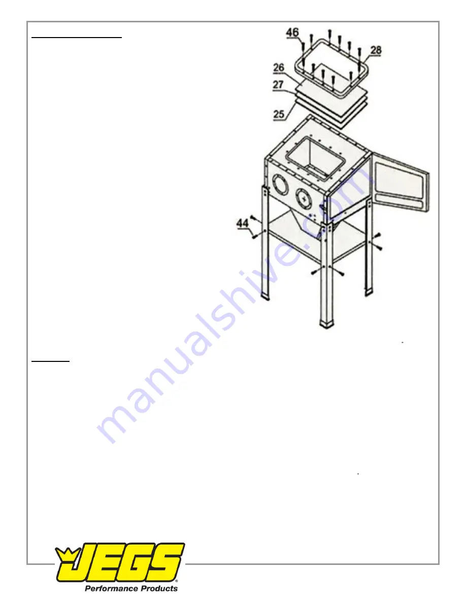
Lower Shelf and Window 

1. Install the Lower Shelf (2) with the Flange Bolts and 
nuts M6x12 (44). 
 
2. Layer the Window Protective Film (25), Glass (27), 
Acrylic Glass (26) and Frame (28) over the opening on 
the Cabinet Top Plate and secure in place with the 
Flange Bolts and Nuts M5x25 (46). 


Note:

 This air tool may be shipped with a protective plug covering the air inlet. Remove this plug before set up  


Air Supply 
WARNING! To prevent serious injury from explosion: 

Use only clean, dry, regulated, compressed air to power this tool. Do not use oxygen, carbon dioxide, combustible 
gases, or any other bottled gas as a power source for his tool. 
 
1. Incorporate a filter, regulator With pressure gauge, dryer, in-line shutoff valve, and quick coupler for best service

. An 

in-line shutoff ball valve is an important safety device because it controls the air supply even if the air hose is 
ruptured. The shutoff valve should be a ball valve because it can be closed quickly. 
 
Note: 

An oiler system should not be used with this tool. The oil will mix with the material being propelled, causing tool 

to clog. 
 
2. Attach an air hose to the compressor's air outlet. Connect the air hose to the air inlet of the tool. Other components, 
such as a coupler plug and quick coupler, will make operation more efficient, but are not required  
 

WARNING!


TO PREVENT SERIOUS INJURY FROM ACCIDENTAL OPERATION: 

Do not install a female quick coupler on the tool.

 Such a coupler contains an air valve that will allow the air tool to 

retain pressure and operate accidentally after the air supply is disconnected. 

Note:

 Air flow, and therefore tool performance, can be hindered by undersized air supply components. The air hose 

must be long enough to reach the work area with enough extra length to allow free movement while working. 


                                         1-800-345-4545   jegs.com


Summary of Contents for 81500

Page 1: ...Keep hair clothing and gloves away from moving parts Loose clothes jewelry or long hair increases the risk of injury to persons as a result of being caught in moving parts 3 Avoid unintentional starting Be sure the trigger is released before connecting to the air supply Do not connect the tool to the air supply with the switch on 4 Remove adjusting keys and wrenches before turning the tool on A wr...

Page 2: ... measure worker exposures 3 Use containment methods such as blast cleaning machines and cabinets to control hazard and protect adjacent workers from exposure 4 Practice good personal hygiene to avoid unnecessary exposure to silica dust 5 Wear washable or disposable protective clothes at the work site Shower and change into clean clothes before leaving the work site to prevent contamination of cars...

Page 3: ...s manual including all text under subheadings therein before set up or use of this product Note For additional information regarding the parts listed in the following pages refer to the Assembly Diagram near the end of this manual Light Clamps Attach the Light Clamps 35 to the inside of Cabinet Rear Plate 19 using the Bolts Which are pre assembled on the Light clamps Gloves 1 Secure the Glove Moun...

Page 4: ...ts M6x12 44 to secure the sections in place 1 Attach the Front Cabinet Plate 17 and the Back Cabinet Plate 19 to the top edges of the top plate 16 overlapping the front and back flanges over the edges of the top plate 16 2 Place the Left Cabinet Plate 18 over edges of the Front and Back Cabinet Plates and the Top Plate 3 Place the Door Frame to the other side of the Front and Back Cabinet Plates a...

Page 5: ...witch 21 and Switch Cover 20 on the Cabinet Left Plate 18 With the Bolts pre assembled on the switch housing Install the Door Lock 12 on the Cabinet Front Plate 17 with the bolts and nuts pre assembled on the Door Lock Funnel 1 Place the Funnel Left and Right Plates 7 on the inside flanges of the Funnel Front and Rear Plates 6 and secure in place with the Flange Bolts and nuts M6x12 44 2 Slide the...

Page 6: ...en Frame 10 Steel Screen 11 on top of the Funnel and secure the assembly to the bottom of the Cabinet with Flange Bolts and Nuts M6x35 41 2 Attach the Abrasive Gun Air Inlet Hose to the inside lower right side of the Cabinet and the Hose Inlet Fitting 42 to the outside using the Bolts and Nuts M6x35 41 3 Slide the Suction Hose 8 end into the Funnel through the Screen 1 800 345 4545 jegs com ...

Page 7: ...ice because it controls the air supply even if the air hose is ruptured The shutoff valve should be a ball valve because it can be closed quickly Note An oiler system should not be used with this tool The oil will mix with the material being propelled causing tool to clog 2 Attach an air hose to the compressor s air outlet Connect the air hose to the air inlet of the tool Other components such as ...

Page 8: ...G TO PREVENT SERIOUS INJURY FROM ACCIDENTAL OPERATION Tum off the tool detach the air supply safely discharge any residual air pressure in the tool and release the trigger before performing any inspection maintenance or cleaning procedures TO PREVENT SERIOUS INJURY Do not adjust or tamper with any control or component in a way not specifically explained within this manual Improper adjustment can r...

Page 9: ...o not aim the nozzle at your fingers or the Blast Gloves If Gloves are punctured or you feel air blowing in the Glove replace the immediately Do not use a damaged or punctured Glove 12 If the tool requires more force to accomplish the task verify that the tool receives sufficient unobstructed airflow CFM and increase the pressure PSI output of the regulator up to the maximum air pressure rating of...

Page 10: ...the regular checks and maintenance explained as part of the regular operation of the air operated tool 1 Daily Air Supply Maintenance Every day maintain the air supply according to the component manufactures instructions Drain the moisture filter regularly Performing routine air supply maintenance will allow the tool to operate more safely and will also reduce wear on the tool 2 After use empty th...

Page 11: ...maged valve or housing 4 Dirty worn or damaged valve 1 Check for incorrect alignment and uneven gaps If cross threaded disassemble and replace damaged parts before use 2 Tighten housing assembly If housing cannot tighten properly internal parts may be misaligned 3 Replace damaged components 4 Clean or replace valve assembly Abrasive media not effective Abrasive media has become worn down from use ...

Page 12: ...FIED TO MAKE ANY REPAIRS TO THE PRODUCT OR THAT HE OR SHE IS QUALIFIED TO REPLACE ANY PARTS OF THE PRODUCT IN FACL THE MANUFACTURER AND OR DISTRIBUTOR EXPRESSLY STATES THAT ALL REPAIRS AND PARTS REPLACEMENTS SHOULD BE UNDERTAKEN BY CERTIFIED AND LICENSED TECHNICIANS AND NOT BY THE BUYER THE BUYERASSUMESALL RISKAND LIABILITY ARISING OUT OF HIS OR HER REPAIRS TO THE ORIGINAL PRODUCT OR REPLACEMENT P...

Page 13: ...embled on 13 12 12 Door Lock with Bolts 1 37 Light Tube 1 13 Door with Foam Seal 14 1 38 Transformer 1 14 Foam Seal 1 39 Gloves 2 15 Door Frame 1 40 Abrasive Blasting Gun 1 nozzle 1 16 Cabinet Top Plate 1 41 Flange Bolt and Nut M6x35 16 17 Cabinet Front Plate 1 42 Air Inlet Fitting with Rubber Seal 18 Cabinet Left Plate 1 43 Vacuum Suction Hose 1 19 Cabinet Rear Plate 1 44 Flange Bolt and Nut M6x1...

Reviews: