background image


MAINTAINENCE 

1. Periodically check the tightness of mounting bolts and electrical connections. Remove all dirt or corrosion and always 
keep clean. 
2. Do not attempt to disassemble the gear box. Repairs should be done by the manufacturer or an authorized repair 
center. 
3. The gear box has been lubricated using a high temperature lithium grease and is sealed at the factory. No internal 
lubrication is required. 


REPLACING THE WIRE ROPE 

1. If the wire rope has become worn or is beginning to show signs of strands breaking it must be replaced before being 
used again. To do this, remove the defective rope by free spooling. Remove the M5 x 5mm bolt on the drum and 
release the rope. 
2. Insert the end of new rope and secure the M5 x 5mm bolt tightly. 
3. Engage the clutch and re-spool the new rope on the drum keeping tension on the rope as it spools. Ensure that the 
rope is re-spooling in the under wind position. 


WARNING 

- Only replace the wire rope with the identical replacement part recommended by the manufacturer.


SYMPTOM


POSSIBLE CAUSE


SUGGESTED ACTION


Motor does 
not turn on


-Switch Assembly not 
connected property 
 
-Loose battery cable 
connections 
 
-Solenoid malfunctioning 
 
-Defective Switch Assembly 
 
-Defective motor 
 
-Water has entered motor


-Insert Switch Assembly all the 
way into the connector. 
 
-Tighten nuts on all cable 
connections. 
 
-Tap solenoid to loosen contacts. 
Apply 12volts to coil terminals 
directly. A clicking indicates 
proper activation. 
 
-Replace Switch Assembly 
 
-Check for voltage at armature 
port with switch pressed. If 
voltage is present replace motor. 
 
-Allow to drain and dry. Run in 
short bursts without load until 
completely dry.


Motor runs but 
cable drum 
does not turn


-Cam Ring (clutch) 
not engaged


-Move Cam Ring to the in 
position. If problem persists, a 
qualified technician needs to check 
and repair.


Motor runs 
slowly or 
without normal 
power


-Insufficient current or 
voltage


-Battery weak, recharge. Run 
winch with vehicle motor running. 
 
-Loose or corroded battery cable 
connections. Clean, tighten, or 
replace


Motor 
overheating


-Winch running time too 
long


-Allow winch to cool down 
periodically.


Motor runs in 
one direction 
only


-Defective or stuck 
Solenoid 
 
-Defective Switch 
Assembly


-Tap solenoid to loosen contacts. 
 
-Repair or replace solenoid. 
 
-Replace Switch Assembly


TROUBLESHOOTING 


                                         1-800-345-4545   jegs.com


Summary of Contents for 92600

Page 1: ... 28 5 32 M 1 5 3 5 5 9 8 7 10 INTRODUCTION Congratulations on your purchase of a JEGS winch Designed and built to strict specifications With proper use and maintenance your winch should bring you years of satisfying service WARNING Read study and follow all instructions before operating this device Failure to heed these instructions may result in personal injury and or property damage Your winch c...

Page 2: ...onnect the battery 4 1 and motor 5 9 leads Connect the red positive to the in facing terminal marked on the motor and the black Negative to out facing terminal marked on the motor Then connect the red positive lead from the power switch to the positive terminal of the vehicles 12 volt battery Connect the black negative lead from the power switch to the negative terminal of the battery Fig 1 Fig 2 ...

Page 3: ...1 800 345 4545 jegs com ...

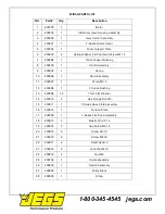
Page 4: ...1 Drum Assembly 11 200007 1 Screw M5 5 12 200008 1 T Series Bushing 13 200009 1 2 Thick Flat Washer 14 200010 2 Hex Flange Nut M5 15 200011 1 T Series Base Plate Assembly 16 200012 1 Tension Plate 17 200500 1 T Series F W Knob Assembly 18 200013 1 Elastic Pin 2 5 14 19 200014 2 Cap Screw M6 16 20 200015 2 Screw M5 10 21 200016 2 Screw M8 30 22 200017 2 Flat Washer 8 23 200018 2 Lock Washer 8 24 20...

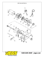
Page 5: ...Winch Assembly Drawing 1 800 345 4545 jegs com ...

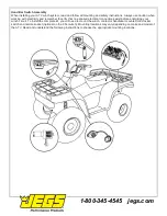
Page 6: ...d electrical connections exist before energizing your winch circuit To install the complete kit you will need to mount the winch contactor handlebar mounted mini rocker switch and remote socket optional on the 2 5ci winch Mounting locations may vary depending on make and model of the ATV Read and understand the following instructions to choose the appropriate mounting locations 1 800 345 4545 jegs...

Page 7: ... on the handle bar Do not tighten over any hoses or cables Once the handle bar switch is mounted route the two bullet terminal wires back to where the contactor will be mounted Splice the end of the red 20ga wire to key controlled electrical wire of the ATV Using a test light locate a suitable wire from the ATV key switch The wire should only have power when the key is in the ON position Use a tes...

Page 8: ...and should not be made Duration of winching pulls should be kept as short as possible If the motor becomes uncomfortably hot to the touch stop winching immediately and let is cool down for a few minutes Do not pull for more than one minute at or near the rated load CAUTION If the motor stalls do not maintain power to the winch Electric winches are designed and made of intermittent use and should n...

Page 9: ... and the winch Fig 3 2 Short pulls from an angle can be used to straighten the vehicle Long pulls should be done with the wire rope at a 90 angle to the winch vehicle When pulling a heavy load place a blanket or jacket over the wire rope five or six feet from the hook In the event of a broken cable it will dampen the snap back For additional protection open the hood of the vehicle as shown in Fig ...

Page 10: ...enly and tightly around the drum The vehicle that is being winched can be slowly driven to add assistance to the winching process Avoid shock loads keep the wire rope under tension p The vehicle to be winched should be placed in neutral and the emergency brake released Only release the brake pedal when under full tension Avoid shock loads to the winch This can damage the winch rope and vehicle q T...

Page 11: ...tor does not turn on Switch Assembly not connected property Loose battery cable connections Solenoid malfunctioning Defective Switch Assembly Defective motor Water has entered motor Insert Switch Assembly all the way into the connector Tighten nuts on all cable connections Tap solenoid to loosen contacts Apply 12volts to coil terminals directly A clicking indicates proper activation Replace Switch...

Reviews: