


Page 4
INSTALLING THE WIRE
The MIG100 should be used with a 4
” wire spool only. To install the wire spool follow the procedure listed below:
1. Open the door of the welder and remove the wing nut
(PIC. C1)
and spacer from the Wire Spool Spindle.
2. Slide the 4
” Wire Spool onto the Wire Spindle and reinstall the spacer and wing nut.
THREADING WELDING WIRE THROUGH THE DRIVE MOTOR TO THE WELDING GUN
This welder uses only self-shielding flux-core wire in either 0.030" or 0.035" size (0.8 or 0.9mm). To install the welding
wire follow the procedure outlined below:
1. Turn the power switch to the off position and unplug the welder from the power supply.
2. Remove the contact tip and nozzle from the end of the torch.
3. Ensure that the drive roller is installed in the proper position for the wire size being used.
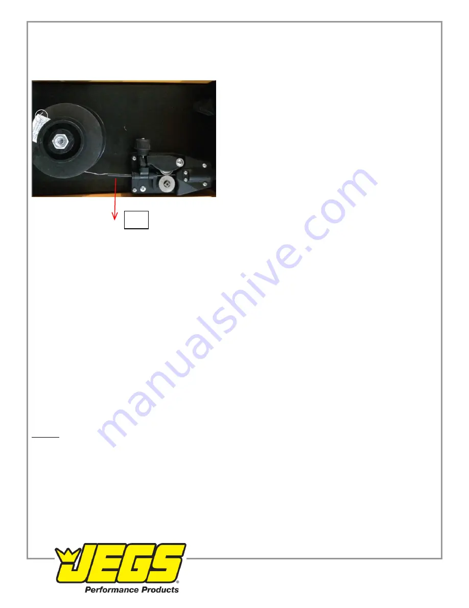
4. Unlock the Pressure Adjuster
(PIC. C1)
and lift up on the Rocker Arm
(PIC. C2)
. Ensure that the wire drive
roller is appropriate to the welding wire size see the previous section describing the installation of the drive
roller. The drive roller comes installed for 0.035" (0.9mm) wire.
5. Pull out the welding wire from the wire spool carefully.
NOTE:
Do not let go of the wire or the entire spool could
unravel.
6. Cut off a small piece of the curved segment at the front of welding wire and straighten the welding wire to
approximately 3" long.
7. Thread the welding wire through the Guide Pipe
(PIC. C4)
and over the wire Drive Roller and into the torch
hole.
8. Reattach the Rocker arm and reset the Pressure Adjuster.
9. Turn on the machine and set the wire speed.
10. With the gun pointed away from you and others, depress the trigger to begin feeding wire.
NOTE:
Watch the
drive roller to see if any slippage is occurring between the roller and wire, if so, turn the machine off and tighten
the Pressure Adjuster turn and test again.
11. Once the wire exits the end of the torch, install the contact tip and nozzle. Cut the wire about 1/4" from the end
of the contact tip.
USAGE
Your MIG100 can be used to perform a large number of different types of welds, all of which will require practice and
testing before using on an actual project piece. This following welding process is just a baseline to get you started.
1. Connect your ground clamp to the work pieces that are to be welded. Make sure the ground clamp contacts are
placed on a clean piece of metal free of paint, grease, rust, oils, etc. It is recommended to place your ground
clamp as close to the weld area as possible.
2. Assess your weld area and make sure the welding area is also cleaned of any paint, grease, rust, oils, etc.
3. Plug in the welder and switch to the ON position.
4. Depress the Welding Gun trigger pointing the welding gun away from your body and then let go of the trigger
and cut the wire back to ~1/4" stick out length.
5. Wearing your welding helmet, gloves, long sleeve shirt and pants, put the end of the wire sticking out of the gun
into the joint to be welded.
6. Position the Welding Gun so that it is perpendicular to the base metal with 15~20° tilt back.
1-800-345-4545 jegs.com
C4


