background image


Page 20 


How to operate 


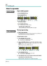
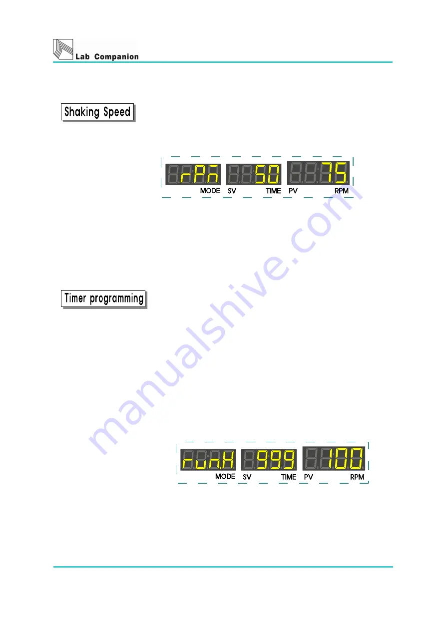
Input shaking speed 


1.


Press SHAKER/SET key. 


2.


Press UP/DOWN key. 


Input RPM. 


3.


Press Enter Button. 


    Finish to set value. 


4.


Press START/STOP key.


  Shaking starts in clockwise rotation. 


 Recall function of RPM value 

- Previous RPM value starts if new RPM is set again. 


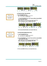
Timer programming   
 

1. Time Programming   

- Programming time can not be done during shaking. So, stop shaking by 

pressing START/STOP key and start programming. 


1) Input total run time 


1.


Press SHAKER/SET key Twice. 


This section is for setting total run time. 


¡run.H¡ shown on MODE display. 

 
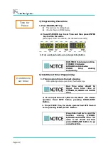
2.


Press  UP/DOWN  Button  to  set  Time  and  then  press 
ENTER  key  to  store  the  value.  
(Max  Input  Time:  1~999 
hours) 
After setting the value, TIMER LED is on. 


3.


Press SHAKER/SET key. 


This section is for setting minute and seconds. 


¡run.S¡ shown on MODE display 

 
4.


Press UP/Down key to set minute and seconds and then 

press Enter key to store the value.   

(Max Input Time: 10seconds~ 59 minutes 59 seconds) 

Summary of Contents for Lab Companion SK-300

Page 1: ...tain the product s functions and to use it safely Especially be sure to read Safety Precaution carefully before you use this equipment Please keep this operating manual close to the equipment to use it after reading through it once Please place it where the new user can find it easily for the safety use when you hand over or lend the equipment to others ...

Page 2: ...rt names and Controller Instructions Part names and functions 18 Operating and functional element 19 How to operate Input shaking speed 20 Timer programming 20 Time programming 20 Examples of Timer programming 23 Shaker movement indication 24 Chapter 5 Switching Orbital Reciprocation Motion and Stroke width adjustment How to switching orbital reciprocation motion Switching motion orbital to recipr...

Page 3: ...age 3 Chapter 6 Maintenance and Troubleshooting Maintenance 36 Safekeeping and Cleaning 37 Troubleshooting 38 Chapter 7 Specification Specification 41 Chapter 8 Warranty and Service Warranty standard 43 ...

Page 4: ...n supply ph uniformity culture fluid in growth environment Lab Companion shakers are realized perfectly the control and shaking circumstance related to the operator s experimental condition Before using the shaker please comprehend the manual in detail Chapter 1 Introduction is composed as follows Caution about the operating instruction Warning mark of the product Caution for safe operation and re...

Page 5: ...sers from accidents or damage beforehand 2 Defined by the Symbol Mark about the safety caution Warning means that the user may have serious damage and even die by improper handling on this unit C aut i on m eans t hat t he user m ay have m i nor dam age and uni t m ay have physi cal dam age by i m pr oper handl i ng on t hi s uni t Protective Ground Terminal It marks the terminal must be connected...

Page 6: ...ease contact the agent or us in case of the component and the consumable parts of the product will be replaced 5 Do not give a strong shock to the product It becomes the cause of product damage and wrong operations Disclaimer 1 In no event will Jeio Tech industries be liable for any incidental or consequential damages for breach of any implied warranty relating to the product 2 Any special indirec...

Page 7: ... the belt Photo Sensor Photo Sensor can perceive a reciprocating motion As soon as motion is perceived by the sensor the shaking system stops at the position exactly Photo sensor can control the stop function at exact position Shaking Control Function Stop function at the exact position When stopping the shaking system the function operates on stopping at the exact position This function contains ...

Page 8: ... at i on RPM can be pr ogram m abl e r el at ed t o t he exper i m ent al condi t i on Rapid Acceleration and Retardation Actualize rapid Acceleration and Retardation using of Velocity Compensation Function and Brake Function At the same time minimize Over Shoot and Under Shoot ...

Page 9: ...ab Companion Be sure to check the electric conditions for electric safe All persons expected to carry out operation installation and maintenance of the unit read and understand the safety information and operating instructions C hapter 2 Transportati on C onfi rm ati on I nstal l at i on are com posed as f ol l ow s Unpacking and Transportation Confirmation Shaker Components Installation Select a ...

Page 10: ...e transportation of the unit 4 Check the parts i e accessories Page 11 of the unit Compensation regulation of damaged unit If the unit is damaged contact the delivery service company immediately 1 Keep the condition as it delivered and wait for the confirmation by the carrier 2 Within 15 days submit an application be made in writing to the delivery service company Do not discard the carton or pack...

Page 11: ...re you purchased Operating manual After unpacki ng check the operati ng m anual I f you di dn t recei ve the operati ng m anual C ontact the di stri butor or the Jei o Tech servi ce center Fuse D uri ng bei ng i n use i f you contact the servi ce center or the di stri butor you w i l l recei ve the servi ce Power Cord Check the power cord matches the supply voltage Spacer Option SK 300 M5 43L 4EA ...

Page 12: ... condition for shakers Room condition of temperature and humidity should be normal as 18 25 below 80 RH 2 Environmental condition Do not expose the machine to direct ray of light 3 Setting place The floor should be on flat and leveled ground 4 Space The machine should be kept at least 1 5m from any illuminators and 20 cm from walls The machine should be operated at the optimum condition for cleann...

Page 13: ...ditions Do not connect the power before checking how to do correct operation 1 C heck i f t he pl ug condi t i on and el ect r i c w i r es ar e norm al 2 Check the connection of ground wire Check the power plug to find if the electric conditions are correct The voltage fluctuation should be within 10 ...

Page 14: ...achi nes broken by w r ong oper at i on Si gnal W or d i s used i n t he operat i on m anual f or saf e and pr oper oper at i on and keeps user s f r om bei ng dam aged by acci dent s Each Sym bol M ar k i s i dent i fi ed f ol l ow i ng t o t he degr ee of i m por t ance and danger Pay at t ent i on t o t he Al er t and Not i ce i n t he m anual t o avoi d f romany acci dent s ...

Page 15: ... use the machine near to places where explosion can be happened due to organic evaporating gases Explosive materials Acid Esther Nitro compound Inflammable materials salt peroxides inorganic peroxide salt acids Put off the power plug if some sounds and smell smokes are happened Do not expose the machine in direct sunlight Do not use the machine at places where moisture is high and flooding can be ...

Page 16: ... vibrate it It can cause damage to the machine Do not clean the machine with solvent abstergent Use smooth cloths Cleaning with solvent can cause fire and deformity Do not touch the shaking table while the machine is operated Stop the machine by using Start Stop button and do necessary works Do not put anything near to the turning radius of the machine while operation Turning radius of the machine...

Page 17: ... the machine after checking chapter 4 for 2 3 times Please do trial test of the machine without loading any sample flask on it Please do contact us if you have request while using the controller Contents of chapter 4 Parts name and function Operating and Functional element How to operate Input shaking speed Timer programming SHAKER Movement indication ...

Page 18: ...otion is performed 2 Receptacle with Fuse Electric Socket with fuse 3 Foot Supporter of the body The supporter can be adjustable its height 4 Body Fly Wheel system is equipped inside the body 5 Control Panel Shaking controller power switch and LED signal lamp are set 5 4 2 1 3 ...

Page 19: ...It is ON once time for clockwise rotation is set B WARD LED It is ON once time for clockwise rotation is set PAUSE LED It is ON once time for pause is set 5 Adjust keys UP key To increase value value moves faster on pressing and holding DOWN key To decrease value value moves faster on pressing and holding Enter key To store value or finish set 6 SHAKE SET To set shaking speed and timer 7 START STO...

Page 20: ...stop shaking by pressing START STOP key and start programming 1 Input total run time 1 Press SHAKER SET key Twice This section is for setting total run time run H shown on MODE display 2 Press UP DOWN Button to set Time and then press ENTER key to store the value Max Input Time 1 999 hours After setting the value TIMER LED is on 3 Press SHAKER SET key This section is for setting minute and seconds...

Page 21: ...alue F WARD LED is ON 3 If not use F Ward function do not press Enter key 3 Programming Backward time 1 Press SHAKER SET key This section is for setting Time Backward bAc S shown on MODE display 2 Press UP DOWN key to set Time and then press ENTER key to store the value Max Input Time 10 seconds 59 minutes 59 seconds After setting the value B WARD LED is ON 3 If not use B Ward function do not pres...

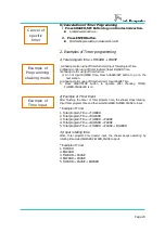
Page 22: ...program time the shaker stops 2 If not input time of F Ward or B Ward the shaker operates fixed RPM before pressing START STOP Button 3 If input PAUSE Time the shaker operates fixed RPM forward before pressing START STOP Button RUN TIME Total program time F WARD Clockwise B WARD Anticlockwise PAUSE Stop shaking temporarily Run Time value should be bigger than total time of F WARD B WARD and PAUSE ...

Page 23: ...ut PAUSE Time 5 Press START STOP button to operate after checking TIMER F WARD PAUSE LED is on 2 Example of Timer Input After finishing the timer of Total program time the shaker stops rotating Input Total program time and then select B WARD F WARD PAUSE to input Example of Timer 1 Total program Time F WARD 2 Total program Time B WARD 3 Total program Time F WARD PAUSE 4 Total program Time B WARD P...

Page 24: ...cation This Function is for displaying the presnt shaking table When maintaing rpm the display starts a circular movement Forward accelation Forward deceleration Backward accelation Backward deceleration Shaking indication on LED ...

Page 25: ...ing or from Reciprocating to Orbital Furthermore Stroke length can be adjusted so that your valued experiment is highly efficient Please choose proper motion and stroke length for optimal experiment Chapter 5 How to switch orbital motion to reciprocating motion SK 300 SK 600 SK 71 How to change the stroke width adjustment SK 300 SK 600 SK 71 ...

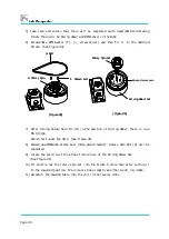
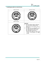
Page 26: ...2 Remove M5 23L Spacer 13mm spanner from the upper vibrating frame The upper vibrating frame is designated to move as the orbital motion 3 Install M5 43L Spacer 13mm spanner into the lower vibrating frame The lower vibrating frame is designated to move as the reciprocating motion 4 Reinstall the Shaking table onto the unit in the reverse order Make sure that a space M5 43L complied with our standa...

Page 27: ...ibrating frame The upper vibrating frame is designated to move as the orbital motion 3 Install M5 43L Spacer 13mm spanner into the lower vibrating frame The lower vibrating frame is designated to move as the reciprocating motion 4 Reinstall the Shaking table onto the unit in the reverse order Make sure that a space M5 43L complied with our standard dimension before using It may cause serious damag...

Page 28: ...ing table 2 Remove M5 35L Spacer 13mm spanner from the upper vibrating frame Figure Inside of Vibrating Frame 3 Install M5 35L Spacer 13mm spanner to the lower vibrating frame The lower vibrating frame is designated to move as the reciprocating motion 4 Reinstall the Shaking table onto the unit in the reverse order It may cause serious damage to the unit if it s too much forced to install above pa...

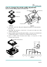
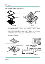
Page 29: ... cover B See Figure 1 3 Loosen 2 ea M5x15 wrench bolt 4mm wrench handle in the position of Bracket C 2 ea 5mm knot 8mm spanner in the position of Bracket D See Figure 2 4 Loosen 4 ea M5X12 wrench bolt 4mm wrench handle in the position of Frame Fixture E See Figure 2 B Body Cover A Shaking Table Figure 1 Figure 2 Figure 4 Upper Bottom Vibrating Frame set Figure 3 Driving Wheel C Bracket D Bracket E...

Page 30: ...m Wrench bolt under the Hole See Figure 5 8 Remove 4ea M5X10mm wrench bolt 4mm wrench handle Rotary Spin Set H will be separated 9 Locate the position of the stroke fixture hole of the Driving Wheel Set See Figure 6 10 Fit and Fix out the rotary spin set into the stroke fixture hole after setting it to the required position The correct stroke length can either be 20 30 40mm 11 Reinstall the shakin...

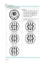
Page 31: ...nge to be desired as in the picture take the right position of the driving wheel onto the system unit 2 Fit and fix out the 4ea M5x10mm wrench bolt 4mm wrench bolt handle into the rotary spin set of the fixture hole according to each stroke Fixture hole consists of 4 holes each stroke in the position of square points ...

Page 32: ...Loosen 2 ea M5x15 wrench bolt 4mm wrench handle in the position of Bracket C 2 ea 5mm knot 8mm spanner in the position of Bracket D See Figure 2 4 Loosen 4 ea M5x8 wrench bolt 4mm wrench handle in the position of Frame Fixture E See Figure 2 B Body cover A Shaking Table Figure 1 C Bracket D Bracket E Frame Fixture Figure 2 Upper Bottom Vibrating Frame F RPM Sensor Shaking System Unit Body Figure 3...

Page 33: ...l There is 4 ea M5X10mm wrench bolt under the Hole See Figure 5 8 Remove 4ea M5X10mm wrench bolt 4mm wrench handle Rotary Sin Set H will be separated See Figure 6 9 Fit and fix out the rotary spin set into the stroke fixture hole after setting it to the position To be desired for the right stroke which can be possible into 20 30 or 40mm 10 Reinstall the shaking table into the unit in the reverse o...

Page 34: ...ht posi ti on of the dri vi ng w heel ont o the systemuni t 2 Fi t and fi x out the 4ea M 5x10m m w rench bol t 4m m w rench bol t handl e i nto the rotary spi n set of the fi xt ure hol e accordi ng to each stroke Fi xture hol e consi sts of 4 hol es each stroke i n the posi ti on of square poi nts Stroke 30mm Stroke 40mm Stroke 50mm Stroke 60mm Stroke 70mm ...

Page 35: ...culture fluid or samples that could be occurred during tests The chapter 6 illustrates trouble that could be occurred operating the unit Please request the service refer to this operating manual when trouble occurs Maintenance Weekly Monthly Quarterly Annually Safekeeping and Cleaning Safekeeping way Exterior cleaning Interior cleaning Troubleshooting Main power Mechanical shaking system ...

Page 36: ...e abi l i t y of the product Check the main power and plug Refer to the chapter 2 installation Check that the setting values and are correctly inputted to press the buttons Make a routine check weekly monthly Check the shaking and timer functions of the controller Check the incubated shaking funtion Make a routine check monthly annually Follow the safekeeping way and maintenance standard to care f...

Page 37: ...eutral detergent 2 Wipe with a dry cloth the LED screen Interior cleaning 1 Please turn off the power switch 2 Take off the platform connecting with the shaking table and then remove interior dust or obstacle 3 Clean up the body using a soft and wet cloth with neutral detergent 4 Wipe with a dry cloth C l eani ng t he i nteri or of uni t m ay cause dam age on syst em or any other part s B e carefu...

Page 38: ...are cut request the service 5 Exchange the fuses installing on the back side of unit Refer to Page 18 6 If the problems do not solve request the service Fuses ar e of t en bur nt out The fuses do not fit the main power The main power might be cut or aparted Humidity might inflow into the main power inserting part 1 Check the voltage and ampere of fuses Model Capacity SK 300 250V 3 15A SK 600 250V ...

Page 39: ...O P but t on but does not w or k Setting values of the controller trouble 1 After pressing SHAKE SET button to input RPM setting value press START STOP button to check operating condition 2 If the problems do not solve request the service Trouble related with mechanical shaking system Trouble Causes Solution Occur trembleing when acceleration deceleration and uniform velocity The shaker is not equ...

Page 40: ...firm the shaker s specification and circuit diagram to check the unit s functions Read this to know its features and specification so test to meet its property The circuit diagram illustrates the shaker s component circuit Specification ...

Page 41: ... i m e 999hr 59m i n 59sec Pause For w ar d Backw ar d M ax 59m i n 50sec M i n 10sec Driving system Br ushl ess D C m ot or w i t h f eedback cont rol Body Steel 3 2t 2 0t powder coating Material Platform Anodi zed al um i numpl at e 4 0t External 410 X 490 X 160m m 510 X 595 X 160m m 82 0 X6 10 X17 0m m Size WXDXH Platform 350 X 350m m 450 X 450m m 755 X 481m m Electric requirements AC 100V 50 6...

Page 42: ...anty and Service Jeio Tech s shakers can be protected by our warranty and service standard Except for the presented standards others would not be warranted Warranty standard General matter Warranty exception Service contact ...

Page 43: ...ot under the authority of service of Jeio tech fixed or changed parts of the machine If the broken machine is due to customer s fault 3 Contact your regional dealer for after service General matter The term of guarantee about responsibility on manufacture is 1 year from purchase work under Warranty exception Charge within the term of warranty if as follows Purchase date Serial number A trouble par...

Reviews: