background image

0DQXDO1R

00HAA0001203 (Rev 1.0)


1.0 Safety 

Summary of Contents for TC-ME-025

Page 1: ... OPERATING MANUAL TEMPERATURE CHAMBER TABLE TOP MODEL TC ME 025 065 100 MANUAL NO 00HAA0001203 Rev 1 0 ...

Page 2: ......

Page 3: ... your unit or the information in this manual contact our Sales Department If your unit fails to operate properly or if you have questions concerning spare parts or Service Contracts contact our Service Department LJXUH Please locate the identification label on the right side of the instrument Fill in the information found on the identification label in the spaces provided above in Figure A Refer t...

Page 4: ...m eng images ISO Jeiotech 1 jpg to view a copy of our certificate Disclaimer Jeio Tech Co Ltd is committed to a continuing program of product development and improvement and reserves the right to change information such as specifications appearance and dimensions described in this document without notice Copyright No part of this manual may be reproduced or transmitted in any form or by any means ...

Page 5: ...ignal word panels 1 3 2 Safety symbols 1 3 3 Miscellaneous none safety symbols used in manual 1 4 Where to Locate Safety Labels on the Temperature chamber 1 4 1 TC ME PE 025 065 100 1 5 Precautions for Temperature chamber 1 5 1 Warning statements 1 5 2 Caution statements 1 6 Responsibility 1 6 1 General responsibility 1 6 2 Operator responsibility 1 6 3 Maintenance responsibility 1 6 4 Reporting a...

Page 6: ...x Number of the mountable shelves distance between shelves 22 2 3 4 How to use water tank 23 2 3 5 Main Switch Panel 23 3 0 Installation 25 3 1 Uncrating and inspecting the unit 26 3 1 1 Inspecting before removing outer container 26 3 1 2 Removing the unit from shipping container 26 3 1 2 1 Phase 1 Removing the outer container 27 3 1 2 2 Phase 2 Removing the unit from wooden crate 30 3 2 Unit comp...

Page 7: ...2 3 2 RESERVE 46 4 2 3 3 Graph 46 4 2 4 SETUP Screen 47 4 2 4 1 Password 47 4 2 4 2 TROUBLE Shoot 47 5 0 How to use Software 49 5 1 Initial display 50 5 2 Separate operating display 51 5 3 Program setting display 53 5 4 Graph display 58 6 0 Accessories 61 6 1 Accessories and Options List 62 7 0 Appendix 63 7 1 Technical Specification 64 7 2 Warranty 65 7 2 1 Service under Warranty period 65 7 2 2 ...

Page 8: ... LY Ý OO 5LJKWV 5HVHUYHG HLR 7HFK R WG ...

Page 9: ... 0DQXDO 1R 00HAA0001203 Rev 1 0 1 0 Safety ...

Page 10: ...es required data for receiving unpacking inspecting and setup of the unit We can also provide the assistance of a factory trained technician to help train your operator s for a nominal charge This section includes instructions checks and adjustments that should be followed before commencing with operation of the Temperature chamber These instructions are intended to supplement standard laboratory ...

Page 11: ...peration of this equipment It is not practical to list all unsafe conditions Therefore if you use a procedure that is not recommended in this manual you must determine if it is safe for the operator and all personnel in the proximity to the equipment If there is any question of the safety of a procedure please contact Jeio Tech before starting or stopping the equipment This equipment contains high...

Page 12: ...ety messages or property damage messages and designate a degree or level of hazard seriousness It consists of three elements a safety alert symbol a signal word and a contrasting rectangular background The following signal word panels are in accordance with ANSI Z535 4 2007 and ISO 3864 standards Indicates a hazardous situation which if not avoided will result in death or serious injury Indicates ...

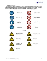
Page 13: ...ssages intended to convey a message without the use of words The following safety symbols are used in this manual Mandatory Prohibition Read manual No direct sunlight Wear a face mask No high frequency noise Wear gloves No corrosive fluid or cleaners Wear goggles No water WARNING Safety Alert Symbol General caution Hand crush or pinch Electrical shock Foot crush Flammable or fire could be caused L...

Page 14: ...raphic representations are intended to convey a message without words or to bring your attention to important information about the use of the incubated shaker or a feature European Union electrical directive compliance Earth ground Relative humidity Note Altitude Good Design designated by Korean government ...

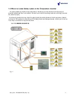
Page 15: ... and how to avoid them All users must read this operating instruction carefully to operate the product properly The following illustrations show where the safety labels should be attached to the Temperature chamber until service of the product is discontinued If the safety labels are damaged please contact your local Jeio Tech office or distributor to request new labels 1 4 1 TC ME PE 025 065 100 ...

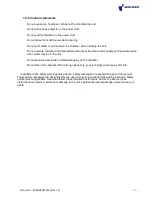
Page 16: ...maged line cords Do not handle or touch electrical cord and electrical parts with wet hands Do not move equipment while it is plugged into the power source Do not use or keep flammable gases near the chamber Do not install the chamber near environments where flammable gas may leak Do not use the chamber near environments where explosion can occur due to organic evaporating gases Do not put explosi...

Page 17: ... request service when water may be in the unit Do not sprinkle insecticide or flammable spray on the chamber Do not clean the chamber with a strong cleanser e g solvent type and use a soft cloth In addition to the safety warnings listed above safety messages are posted throughout the manual These safety messages are designated by the use of a signal word panel followed by text and a safety symbol ...

Page 18: ...ize that every day safety is a vital part of their jobs If your main concern is loss of productivity remember that production is always affected in a negative way following an accident The following are some of the ways that accidents can affect your production l Loss of a skilled operator temporarily or permanently l Breakdown of shop morale l Costly damage to equipment and laboratory samples l D...

Page 19: ...our hands or any part of your body in any dangerous location l NEVER operate service or adjust the equipment without appropriate training and first reading and understanding this manual l Before you start the portable drying conveying system check the following n Remove all tools from the machine n Be sure no objects samples or chemicals are laying on the chamber l If your chamber has been inopera...

Page 20: ...nded electrical outlet that complies with current codes When you have completed the repair or maintenance procedure check your work and remove your tools DO NOT restore power to the chamber until all persons are clear of the area BEFORE you turn the chamber over to the operator for production verify the unit is functioning properly 1 6 4 Reporting a safety defect If you believe that your chamber h...

Page 21: ...0DQXDO 1R 00HAA0001203 Rev 1 0 2 0 Functional Description ...

Page 22: ...resin PCB for automobile Reliability 30 120 0 PCB for mobile phone Reliability 40 80 0 Electronic component Epoxy cure test 40 120 0 Material for lens Reliability 20 30 Part for mobile phone Long term storage at low temperature low humidity Processed part for automobile Measuring moisture contents 25 60 Pharmaceutical Stability test 25 65 Pharmaceutical Long term storage 25 80 OLED Constant temper...

Page 23: ...f Heat test Historic relics Preservation treatment LED Durability test of temperature and humidity Semiconductor component Moisture resistance test 60 90 Cutting oil Constant temperature and humidity test 70 50 Navigator Durability test Display Durability test 70 80 Component for mobile phone Reliability Memory for mobile phone Wet proof Heat test 80 80 Solenoid valve Wet proof Heat test Material ...

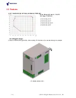
Page 24: ...emp Humid TH Only Temp Range with humid 15 90 C Full range 20 95 rh 45 75 RH at 15Ȕ 40 95 RH at 20Ȕ 20 95 RH at 40 85Ȕ 20 90 RH at 90Ȕ 2 2 2 Elegant design In order to differentiate against the other existing TH chambers the excellent design is selected TC ME PE 025 065 100 ...

Page 25: ...ing alarm à Cable port for running in wires à Basic hole of 50mm diameter cable port is standard equipped on left side of chambers for wiring to the specimen We also provide additional 50 or 80mm diameter cable port Optional à Water tank for easy water supply Maintenance can be done easily from the front side 2 2 5 Safety functions à When the overheat alarm rings for air heater without the user s ...

Page 26: ... Ý OO 5LJKWV 5HVHUYHG HLR 7HFK R WG 2 3 Construction ...

Page 27: ...apacity and better performance Of the unit 5 Access port Basic access port is Ø50mm and each Ø50mm or Ø80mm Access port can be added upon user s request Access port is used for the passing the power cable Thru chamber for the sample test of electronic components or other Devices 6 7 Condensing air ventilation Hole Air ventilation holes perforated plate are located on the left side bottom of the re...

Page 28: ...or user s safety by using magnetic door limit switch It also reduces the radical change of temperature or humidity inside of chamber 13 Shelve 2 shelves are basically provided for the supporting the sample which made of stainless steel Its appearance has a fine view clean body due to electro polishing finish 14 Caster The unit can be placed on a level on the ground Even if it s not even ground by ...

Page 29: ...ration because it cause a residual heat when heating and cooling and lots of a time for the auto tuning However the Nichrome Ni Cr heating element newly adopted has been improved in the response speed resulting in better performance in controlling the temperature and reducing the time for auto tuning And also the heating element for humidity is made of SUS material not to cause some problem in qua...

Page 30: ... 1210 2 3 3 Max Number of the mountable shelves distance between shelves The distance of each groove on the shelf level adjustor is 20mm Max Number of the mountable shelves to each model is between 7 10 units User could purchase additional shelves according to their test conditions Model Max No of mountable shelves Distance between each groove 25L 7 units 20mm 65L 10 units 20mm 100L 10 units 20mm ...

Page 31: ...to to the original position after finish supplying water Water tank Capacity 1 TH ME PE 025 5 0L 2 TH ME PE 065 6 0L 3 TH ME PE 100 9 0L 2 3 5 Main Switch Panel 1 Over Temp limit for Air When the air temperature rises more than Set temperature the second main power Will be shut 2 Over Temp Limit for Water When the water temperature rises more than Set temperature the second power will be shut When...

Page 32: ... Ý OO 5LJKWV 5HVHUYHG HLR 7HFK R WG ...

Page 33: ...0DQXDO 1R 00HAA0001203 Rev 1 0 3 0 Installation ...

Page 34: ...container and packing materials are in re usable condition save them for reshipment if necessary 3 1 2 Removing the unit from shipping container The unit is shipped on a wooden skid with an outer and inner container The wooden outer container is bolted to the shipping skid and has a protective vinyl cover stapled to the container s top Under the outer container the incubated shaker is covered with...

Page 35: ... cover to the wooden crate with a straight blade screwdriver Step2 Lift the vinyl cover off the wooden crate Step3 Inspect the wooden container top for signs of moisture infiltration around the screws Step4 Remove the fourteen 14 7 x 50mm Bugle head screws with a 3Pt Phillips screwdriver See Figure 3 3 Step5 Remove the wooden container top ...

Page 36: ...ure 3 4 Step6 Remove hex head lag screws holding the container sides by using wrench or spanner See Figure 3 4 Figure 3 5 Step 7 Remove the crate front from the crate supports at points A B and C using a hammer and or crowbar See Figure 3 5 ...

Page 37: ...ping crate panel can cause minor or moderate personal injury To avoid injury have assistance in holding and removing the crate panel NAILS STAPLES ARE SHARP Be careful when removing crate panel and supports contact with nails staples could cause minor or moderate personal injury To avoid injury use hammer to bend over or remove and keep hands and other body parts away from nails staples ...

Page 38: ...move the unit from the wooden crate using a forklift Do not use manpower in any cases because it s heavy for men to lift forklift Tool required None Figure 3 7 Step 1 Carefully slide forklift forks under the unit Forks should be set so that outside to outside fork dimension is 800mm See Figure 3 7 Step 2 Slowly lift the unit above the caster blocking and carefully pull the unit out of the crate St...

Page 39: ...cter of the unit If you didn t receive one or more of the components or if the model is incorrect contact your local Jeio Tech office or the distributor from which the unit was purchased COMPONENT QUANTITY RECEIVED Unit 1 Shelf 2 Shelf bracket 4 Operation manual 1 Controller manual 1 Drain hose 1 Access port stopper Access 1 communication software CD 1 RSWLRQDO Cable for communication 1 RSWLRQDO C...

Page 40: ...ufactured as the size of Figure 3 10 It is essential the unit to be situated in an area where there is minimum space 1 0m for the front ward due to 650mm in width of the door Figure 3 10 Items W mm D mm H mm A mm B mm TC ME PE 025 500 760 850 210 452 TC ME PE 065 550 890 1000 245 525 TC ME PE 100 650 1000 1030 270 505 ...

Page 41: ...e than 1 5m from the lighting device and more than 70cm from the wall 3 The floor should be level and of solid construction to prevent from any vibration or a noise 4 Temperature at the location to be installed should be below at 30C 80 RH and the place should be located away from the stove or Heater generating heating source 5 Be careful when moving the unit due to its heavy weight FP ...

Page 42: ... to 30 O C Relative humidity not to exceed 85 Altitude not to exceed 2000m 6 562 feet Keep incubated shaker away from high frequency noise produced by equipment and or machinery such as electrical distribution pa nels welders induction heating mechanism and large amounts of SCR Silicon controlled rectifiers See Section 6 4 Troubleshooti ng Electrical for the effects of high frequency noise Connect...

Page 43: ... is level Figure 3 12 Tool required Step 1 Place the unit in its location Step 2 Lower the foot of each caster by turning the red height adjustment counterclockwise until it hits the floor Turn the height adjustment a quarter turn or more to ensure the unit s weight is taken off the caster This will lock the unit in place Step 3 Place a level on the top of the door and check for level side to side...

Page 44: ...er waste the outlet push soft walled tubing such as vinyl FKM urethane neoprene or silicone over the drain barb until is seated against the collar then tie it with a cable tie as shown below 3 6 Pre start up checks à Make sure all unit and wall outlet electrical connections are tight à Make sure condense drain hose is tightly on hose barb and hose is run to a drain à Make sure caster feet are lowe...

Page 45: ...0DQXDO 1R 00HAA0001203 Rev 1 0 4 0 OPERATION ...

Page 46: ...ol button To start and stop operation To move from running display to MAIN MENU display To move a display to another display such as PARAMETER setting display vertical movement To move previous or next screen in same category To choose display movement in MENU display To enter set value or modify set value To move digit point during modifying set value ...

Page 47: ...horizontal movement To move digit point during modifying set value To move down in MENU or Parameter setting display To decrease value of Arabic numbers or to change text To move up in MENU or Parameter setting display To increase value of Arabic numbers or to change text 5 Individual Screen ...

Page 48: ...r Switch 2 How to Control Press the key then move to Temperature and Humidity input display Input Temperature Use UP DOWN SHIFT KEY to input set value Press key then move to Fix Stop standby screen How to start FIX Run Press key to operate with set value ೫ Fig 1 shows FIX RUN mode when press and Fig 2 displays when pressing key ...

Page 49: ... temperature by specific set value SP FIX STOP It indicates stop of running SP temperature value for running Set the temp value by pressing READY Stand by status Press RUN STOP key for 3 seconds to start operating FIX RUNNING The First Screen FIX RUNNING Unit is running PROCESS TIME It indicates running time of unit IS It indicates number of Inner Signal operation FIX RUNNING The Second Screen PV ...

Page 50: ...KE SET KEY PT NO Set PATTERN No STC Set Start Code SSP S PV T PV SSP Set Start SET POINT USED PT SEG Indicates number of used PATTERN and SEGMENT Input the set value and running time for each SEG and set Time Signal1 2 3 4 5 Time Signal can be adited in SETUP MENU TIME SG EDIT SEGMENT Press SET KEY when the numbers 001 002 below SG in Previous screen are pointed then it moves to the applicable scr...

Page 51: ... Press key and PROG STOP screen shows 2 Press key to activate number of PT No Once it is activated start segment can be set ex If you set PTNO 2 PATTERN starts from 02 3 Press key to finish PTNO set PROG RUNNING starts Press key to start operation ...

Page 52: ...running PID no Refer to figure 12 RM TM Indicates remaining time of operation TS Indicates current condition of Time Signal IS Indicates current condition of Inner Signal PROG RUNNING THE THIRD SCREEN HOLD ON It indicates current holding PT and SEG HOLD OFF It indicates RUNNING status S AL Indicates the current condition of Segment Alarm Signal AL Indicates the current condition of Alarm Signal PR...

Page 53: ...be controlled with RS 485 interface by PC Set protocol as PCLK1 AT TUNING Press KEY for 6 seconds to move to MAIN MENU 2 Switch to the AT TUNING setting screen ೨ It can be set and performed FIX RUN mode ONLY TUNING Accordng to AT ZONE setting performs TUNING and save at PID GROUP automatically depending on setting number AT ZONE When ZONE à AT doing ZONE PID AUTO TUNING operating When SEG à AT doi...

Page 54: ... on Year Month Day and Time SET DATE Current Year Month Day and Time of NOW DATE RESERVE ON set or OFF no delay on 4 2 3 3 Graph MAIN MENU GRAPH GRAPH GRAPH VIEW Temperature and humidity can be expressed as graph of each SEGMENT of each PATTER PTN Set PATTERN number which you want to see SEG It indicates start number of SEGMENT ...

Page 55: ... back to operating disply press SET KEY for 3 seconds or NO KEY for 60 seconds PASSWORD SET KEY pres UP DOWN SHIFT KEY to change password Press SET Key to save 4 2 4 2 TROUBLE Shoot TROUBLE WARN message displays when system is abnormal DI2 DI4 If any trouble happens unit stops ERROR 02 O T WATER over heated humidity heater ERROR 03 DOOR OPEN ERROR 03 W T LEVEL rack of water ...

Page 56: ... Ý OO 5LJKWV 5HVHUYHG HLR 7HFK R WG ...

Page 57: ...0DQXDO 1R 00HAA0001203 Rev 1 0 5 0 How to use Software ...

Page 58: ...This is the initial display of SP790_Multi Monitoring program operated It can make SP790 monitor maximum 30 units easily up download the program and control the saved data figure 1 Initial display Click left button to transfer the separate operating display ...

Page 59: ...ntrolling buttons figure 2 Separate operating display Menu graph Set the displaying for graphs for individual units and save it or not Menu test mode Set the on off for the separate units operating Display current PV SP values Click the left button to transfer the initial display Graph display Controlling button ...

Page 60: ...ect the graphs saving or not and test periods on the below graph setting display Figure 3 graph setting display You can save the graphs After checking the box set files set a files name and a saving route Set the period for the graphs saving ...

Page 61: ...pattern setting display Click the button display the segment setting display Click the button display the pattern information setting display Click the button display the time signal display Click the button upload the Pattern date for setting unit Click the button download Pattern date for a setting unit ...

Page 62: ...You can make out segments for download and confirm the upload date on the below segment setting display Figure 5 Segment setting display You can set TS time signal and WAIT on the below TS WAIT display Figure 6 Time signal setting display ...

Page 63: ...the condition of pattern for download on the below pattern information setting display Figure 7 Set pattern information setting display Set the indicating period for pattern graph Set the conditions of the repeated pattern operating for download ...

Page 64: ...V 5HVHUYHG HLR 7HFK R WG Set a pattern number and a unit for upload Figure 8 Upload pattern number setting display On uploading the setting pattern to a PC display the condition as below Figure 9 Uploading display ...

Page 65: ...00HAA0001203 Rev 1 0 Set a pattern number and a unit for download Figure 10 Download pattern number setting display On downloading set pattern to a PC display the condition as below Figure 11 Downloading display ...

Page 66: ...printing current display Menu view date view display the Date View Menu view list view display the List View Menu set set graph setting the graph display condition Menu zoom in out zoom in zoom in saved graph Menu zoom in out zoom out zoom out saved graph Menu convert excel file converting saved graphic date to excel file 2Q FOLFNLQJ OHIW EXWWRQ FKHFN WKH FOLFNHG ORFDWLRQ GDWD RQ WKH ...

Page 67: ...0DQXDO 1R 00HAA0001203 Rev 1 0 Figure 13 Graph setting display You can confirm current PV SP Date Time on the below Date View display Figure 14 Date View display ...

Page 68: ... files on the below List View display Figure 15 List View display You can convert opened file data to Excel files on the below Excel files creation display The converted Excel files will be saved at the same location as the opened file Figure 16 Excel file creating display ...

Page 69: ...0DQXDO 1R 00HAA0001203 Rev 1 0 6 0 Accessories ...

Page 70: ...Cable 5m 4 Warning Signal Lamp flashing light 5 Wire shelf for 25L 6 Wire shelf for 65L 7 Wire shelf for 100L 8 Perforated shelf for 25L 9 Perforated shelf for 65L 10 Perforated shelf for 100L 11 Access port dia 50mm 12 Access port dia 80mm 15 Stand for 25L 16 Stand for 65L 17 Stand for 100L 18 2 Step Stand for 25L 19 2 Step Stand for 65L 21 Temperature sensor ...

Page 71: ...0DQXDO 1R 00HAA0001203 Rev 1 0 7 0 Appendix ...

Page 72: ...HLR 7HFK R WG 7 1 Technical Specification 1 All specifications are under ambient temperature 20 68එ no load 2 Technical data according to DIN 12880 IEC 60068 3 Up to 98 of the set value Recommended ambient temperature 20 68එ ...

Page 73: ...even during under warranty period User can not be credited by warranty in case of as below If trouble occurs by an act of God If the equipment breaks down due to misusing of available voltage If damage occurs by dropping a product or impact If damage occurs in an appearance by organic solvents such as thinner benzene If damage occurs without following to notice in the manual If damage occurs by fi...

Page 74: ...treet Woburn MA 01801 USA TEL 1 781 376 0700 FAX 1 781 376 0704 E mail nasupport jeiotech com China RM107 No 68 Line 569 Xin Hua Road Shanghai China Postcode 200052 TEL 86 21 62940608 FAX 86 21 62940602 E mail wslee jeiotech com South East Asia No 7A Jalan Kemboja 1 B 2 48300 Bandar Bukit Beruntung Selangor Darul Ehsan Malaysia TEL 60 0 3 60285833 60 0 3 60285825 FAX 60 0 3 60285822 E mail labcomp...

Reviews: