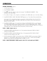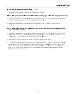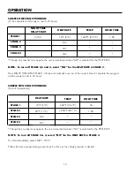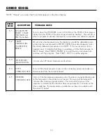
1 . . Remove .the .bottom .front .panel .and .the .upper .and .lower .rear .panels .of .the .furnace . .(Note .the .position .of . .
.
the .vent .louvers .on .the .rear .panels .)
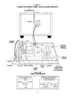
2 . . Note .and .record .the .color .and .location .of .the .wires .on .the .thermocouple .terminals .located .on .the .Main .
.
PC .Board .(Figure .5) .
3 . . Remove .the .thermocouple .wires .from .the .thermocouple .terminals .on .the .Main .PC .Board .(Figure .5) .
4 . . Remove .the .clamp .which .secures .the .thermocouple .to .the .ceramic .terminal .block .located .in .the .upper .rear . .
.
of .the .furnace .(Figure .4) .
5 . . Remove .the .heating .plate .wire .which .crosses .over .the .thermocouple .and .bend .it .out .of .the .way .just .enough . .
.
to .permit .sliding .the .thermocouple .out .of .the .rear .of .the .heating .chamber .(Figure .4) .
6 . . Remove .the .insulating .filler .that .covers .the .holes .in .the .bottom .of .the .upper .section .(Figure .4) . .Straighten .
. . . . .the . .thermocouple .wires .where .they .were .bent .at .a .90
°
.angle .
7 . . Withdraw .the .thermocouple .down .into .the .lower .rear .of .the .furnace .through .the .holes .in .the .upper .and . . .
.
lower .sections . .Discard .thermocouple .assembly .
8 . . Feed .the .new .thermocouple .from .the .lower .rear .of .the .furnace .up .through .the .holes .in .the .upper .and .lower
.
sections .and .into .the .upper .rear .of .the .furnace .
9 . . Bend .the .new .thermocouple .wires .at .a .90
°
.angle .approximately .3 .- .3/8 .inches .(8 .6cm) .from .the .exposed . .
.
tip .of .the .thermocouple . .Be .sure .that .there .are .three .ceramic .insulating .sleeves .between .the .thermocouple . .
.
tip .and .the .bend . .Insert .the .new .thermocouple .into .the .hole .at .the .rear .of .the .heating .chamber .
10 . .Replace .the .heating .plate .wire .that .was .removed .in .Step .3 . .Check .that .there .is .a .ceramic .insulating .sleeve
.
covering .the .thermocouple .wires .where .they .cross .the .heating .plate .wire . .Replace .the .clamp .that .holds .the
.
thermocouple .wires .to .the .ceramic .terminal .block . .Replace .the .insulating .filler .that .covers .the .holes .in .the
.
bottom .of .the .upper .section .
11 . .Connect .the .thermocouple .wires .to .the .thermocouple .terminals .on .the .Main .PC .Board . .Observe .the .color
.
coding .you .noted .in .Step .2 .
12 . .Replace .the .front .panel .and .the .upper .and .lower .rear .panels . .(Be .sure .the .vent .louvers .on .the .rear .panels
.
protrude .out .and .face .down .)
FIELD SERVICE
REPLACEMENT OF THE THERMOCOUPLE ASSEMBLY (PN 18913)
25


