Subject to change without notice!
Installation and Operating Instructions ECOVARIO®114 D
13
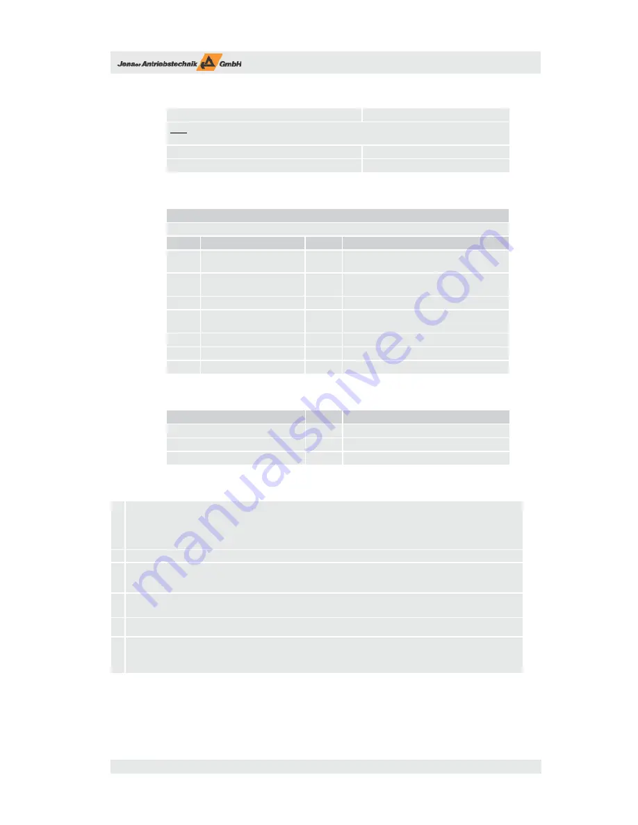
Table 4.4: General technical data, external fuses
70 V DC supply
max. 16 A (slow)
4)
Note:
When the device is used in an UL environment the overcurrent protection equipment has to
comply to UL Class RK5 or UL489!
24 V DC supply
max. 10 A (fast)
External ballast resistance (not accessory resistors DPRxx-xxx)
7)
10 A (fast)
Table 4.5: General technical data, ambient conditions
Ambient conditions
ECOVARIO® is designed for ambient conditions of class 3K3 following EN 50178.
Symb.
Condition
Unit
T
A
Ambient temperature during
operation with nominal load
2)5)
°C
5 – 40
Degree of humidity (not con-
densing)
% rel. F.
5 – 85
p
Air pressure
mbar
860 – 1 060
Cooling
the closed cubicle has to be sufficiently ventila-
ted.
h
Installation altitude
m
up to 1 000 without restriction of power
Installation position
The technical data refer to a vertical position..
Protection class
IP20
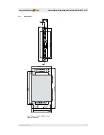
Table 4.6: General technical data, dimensions and weight
Abmessungen und Gewichte
Einh.
ECOVARIO® 114 D
Dimensions w x h x d
mm
42 x 279 x 167
Weight of unit
kg
1.35
Weight with shield set
kg
1.45
Footnotes to tables 4.1 to 4.6
1)
The data refer only to the internal data of the servo amplifi er. Modifi cations of the input voltage due to line supply fl uctuations are not
taken into consideration. That means that with 15 % less input voltage the output data (U
O
, P
O
) have to be reduced by 15 %.
For motors with a low inductivity the motor design for the maximum velocity should be between 25% and 50% below the specifi ed vol-
tages because otherwise the ripple current would be very high. For motors with high inductivities a higher reduction could be necessary
in order to achieve a suffi cient dynamic performance.
The maximum power for both axes together is given by the current carrying capacity of X4A. The maximum total output
power for an operating voltage of 60V
DC
is approx. 900W.
2)
If the heat sink temperature rises over 90 °C or if the ambient temperature passes the upper limit (40°C) the servo amplifi er is switched off
3)
The DC link connection (X4) has no inrush-current limiting. Therefore appropriate circuits have to be integrated in the central power supply.
The power supply also has to be resistant against regenerated energy. It must regulate the DC link voltage during dynamic operation under
the limit U
P
. If the regenerating energy is higher than the energy consumed by all units connected to the DC bus, the power supply must
have a load circuit (ballast resistor).
4)
The value for U
N
represents the nominal DC link voltage. The value for U
P
represents the maximum voltage which can emerge in the DC link
circuit. This voltage is relevant for the dimensioning of the motor winding. Also the dielectric stress at a rectangular voltage of 32 kHz and
a du/dt of maximum 12kV/µs has to be taken into account. U
P
is dependent on the applied voltage.
5)
Environmental conditions for the design of the cabinet. The losses P
VN
refer to nominal operation with I
ONenn
and the maximum output
power P
DC
At deviations the rated loss can be estimated as described.
6)
Rated continuous current for dimensioning. The eff ective value of the motor current must not exceed this value because otherwise some
components will not reach their rated lifetime. This maximum value is part of the fi rmware and cannot be changed (Ixt limit). If the motor
has a lower rated current, this value should be reduced. The maximum time constant of the necessary fi lters depends on the unit, its range
is 1 – 10 s. Also this value cannot be increased but lowered to protect the motor. These two parameters defi ne indirectly the allowed time
of the peak current.


