Installation and Operating Instructions ECOVARIO®114 D
28
Subject to change without notice!
6.4
Safety functions
6.4.1
X8: Restart lock / Safe torque off (STO)
Th e versions ECOVARIO® 114 DR-xx-xxx xxx of the servo amplifi er ECOVARIO® 114 D contain the safety
function „Safe Torque Off “ (STO) according to EN 61800-5-2 and EN ISO 13849-1: 2006. Th e function also
conforms to an uncontrolled stop according to category 0 of IEC 60204-1. Th e safety function is used to
prevent the drive from starting indeliberately.
The „Safe Torque Off “ function does not switch off the power supply of the DC link voltage
of the servo amplifi er. Thus, maintenance of electrical parts of the motor or the servo amp-
lifi er may only be carried out after the drive system has been disconnected from the power
supply.
Th e safety function „Safe Torque Off , STO“ is implemented together with the standard functionality of the
ECOVARIO® 114 D with only a few components related exclusively to the safety function.
Th e STO function meets the requirements to SIL2 or PLd respectively according to EN 61800-5-2 or
EN ISO 13849-1.
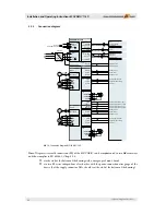
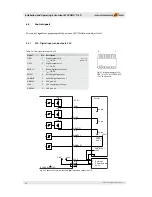
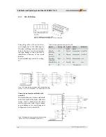
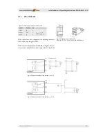
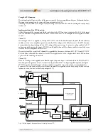
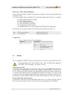
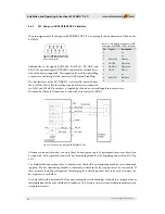
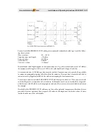
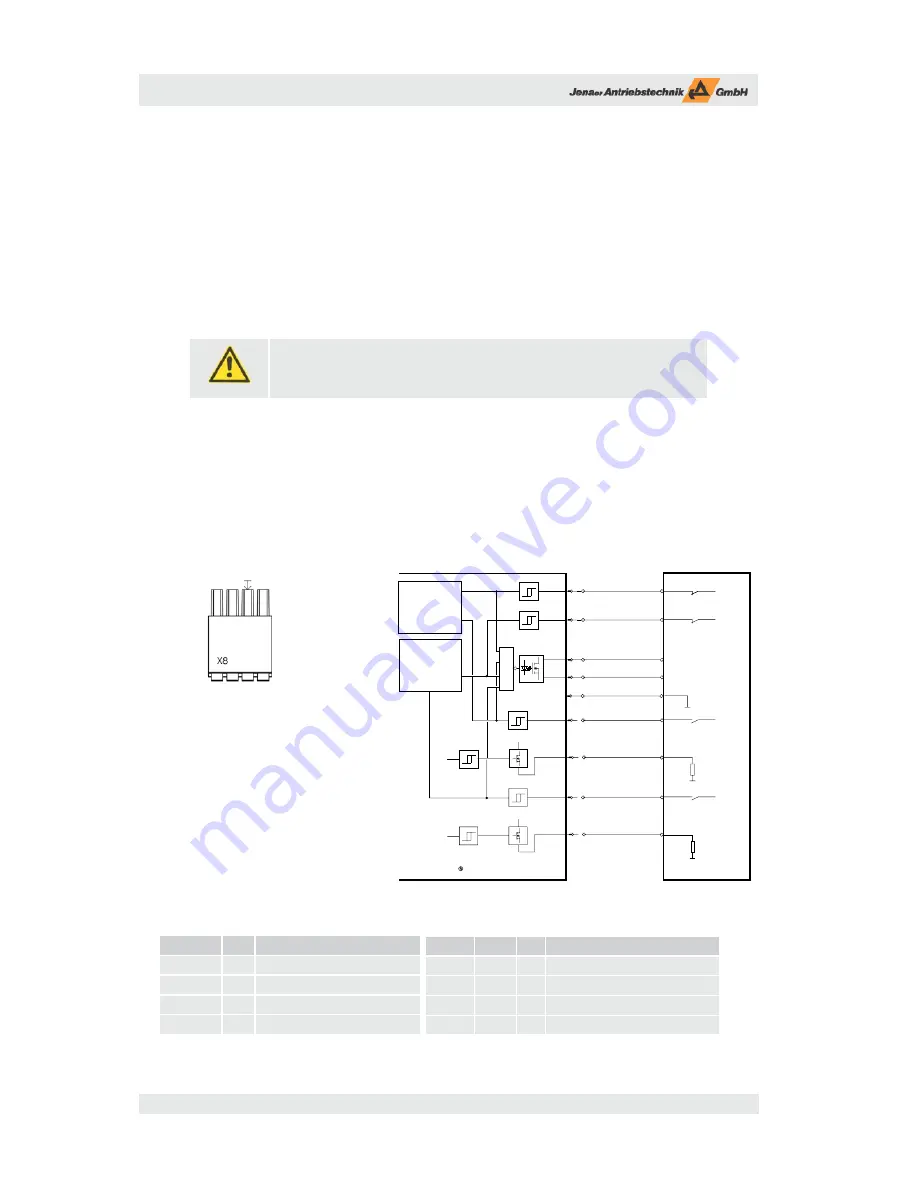
Th e function is established by means of the circuitry shown in Fig. 6.18. Th e signals are lead to the connector
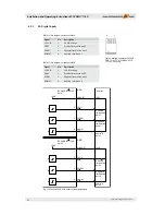
X8. Further, the signals Enable and Ready of connector X1A (axis 1) or X1B (axis 2), respectively, are used.
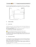
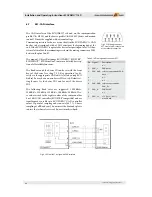
4 1
Fig. 6.17:
Mating connector X8:
FMC 1,5/4-ST-3,81 CN2BD2:
X8SO 17 03 06 7 Phoenix
Signal
Pin
Description
STO IN A
1
STO function axis 1 input
STO OUT A 2
STO function axis 1+2 output contact
STO IN B
3
STO function axis 2 input
STO OUT B 4
STO function axis 1+2 output contact
Table 6.11: Pin assignment connector X8
Fig. 6.18 Connector X8, circuit of the STO function
STO IN A
X8.1
STO IN B
X8.3
Disconnect
Ctrl voltage
Power stages off
ECOVARIO 114 D
Controller
24V
Activate STO axis 1
Output contact STO
axis 1/2
demand value
=0
R
Enable1
Ready1
X1A.5
X1A.3
24V
Enable axis 1
Load
24V
Activate STO axis 2
24V
X1B.3
X1B.1
Enable2
Ready2
24V
Enable axis 2
Load
Axis 1
Axis 2
+24V
+24V
Disconnect
Ctrl voltage
Power stages off
demand value
=0
STO OUT A
STO OUT B
X8.2
X8.4
GND
1
GND
Signal
Conn. Pin Description
Enable1 X1A
5
Enable axis 1
Ready1
X1A
3
Ready for operation axis 1
Enable2 X1B
3
Enable axis 2
Ready2
X1B
1
Ready for operation axis 2
Table 6.11a: Signals used for STO on connector X1A, X1B


