background image

Installation and Operating Instructions ECOVARIO®114 D

30

Subject to change without notice!

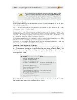
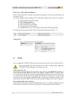
The STO function may only be activated by an automatic control or by manual activation 

if the motor is no longer rotating and the servo amplifer has been switched to „inactive“ 

(24 V are not applied to „Enable“ input). Drives with a suspended load must have an additio-

nal safe mechanical blocking. Via the safety PLC the monitoring contact ASOut bridges the 

safety equipment of the machine (e.g. safety position switches at safety doors). The safety 

area is now protected from indeliberate restart of the device.

Relevant aspects of safety

See also the prescribed use of the servo amplifi er ECOVARIO® 114 D described in chap. 2.6 and the opera-

ting conditions mentioned there.

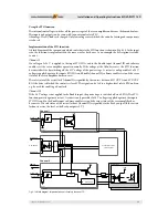
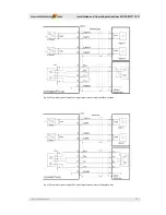
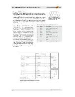
As Fig. 6.19 shows the STO function is implemented by two channels. If a single error occurs, the function 

still remains operative via the other channel.

If the restart lock is active, all driver transistors are in high resistance state. If a current in the motor is pro-

duced by damaged driver transistors the high-pole servo motors as well as the 2-phase servo motors cannot 

start because the necessary rotating fi eld is not created. In the worst case, however, a short hitch can occur 

at the motor shaft  (movement of max. 1/2 pole pair of the motor).
If the internal semiconductor switch is damaged or a cable is broken the safety equipment switches off  the 

drive because in this case the bridging of the safety equipment is not eff ective.

If the restart lock is activated by an automatic control, the control signal must be monitored to make sure 

that the restart lock cannot be activated if the motor is rotating.

Commissioning and checking the STO function

During commissioning of the machine, aft er changing components or restructuring the wiring the function 

of the safety equipment including the STO function must always be checked as described in table 6.12. Th is 

check is also necessary aft er modifi cations of the parameters of aft er a download of a new fi rmware. If none 

of the mentoined cases applies, the function of the safety equipment has to be checked at least once a year. 

Per axis proceed as follows:

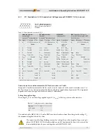
Table 6.12: Checking the functions of the safety equipment

Step Measure

Check

1

Make sure that during the check the dri-

ve can run and stop unrestrictedly

2

Stop drive controlled (target velocity=0)

3

Disable drive (remove Enable signal)

Measure the signal level at the Ready si-

gnal: has to be inactive (0 V).

4

Activate the holding brake, if any

5

Remove the +24 V voltage at STO IN, i.e. 

activate the STO function

6

Open safety equipment (e.g. safety door) 

without interfering with the safety area.

Line contactor must stay „on“.

7

Pull off mating connector X8 from the 

respective servo amplifier.

Line contactor must drop.

8

Plug in mating connector X8. Switch on 

line contactor.

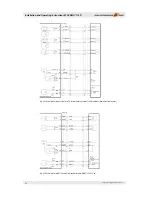
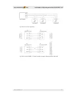
Provided that the checks are carried out regularly as described above, the example circuit below meets the 

requirements of performance level d according to EN ISO 13849-1.

Summary of Contents for ECOVARIO 114 D

Page 1: ...Installation and Operating Instructions ECOVARIO 114 D PROCESS FIELD BUS ...

Page 2: ......

Page 3: ...permission by Jenaer Antriebstechnik GmbH The content of this document has been worked out and checked carefully Nevertheless differences from the real state of the hard and software can never be fully excluded Necessary corrections will be carried out in the next edition ECOSTEP ECOVARIO und ECOLIN are registered trademarks of Jenaer Antriebstechnik GmbH Jena BISS is a registered trademark of iC ...

Page 4: ...Installation and Operating Instructions ECOVARIO 114 D 4 Subject to change without notice ...

Page 5: ... 2 ECOSTEP motors 15 4 4 3 Direct linear motors 16 4 4 4 DC servo motors 16 5 Installation 16 5 1 Mounting 16 5 1 1 Important notes 16 5 1 2 Dimensions 17 5 1 3 Assembly 18 5 2 Electrical installation 19 5 2 1 Important notes 19 5 2 2 EMC compliant installation 19 5 2 3 Connection diagram 20 6 Interfaces 21 6 1 Overview 21 6 2 Control signals 22 6 2 1 X1A Digital inputs and outputs 24 V 22 6 2 2 X...

Page 6: ...interface 44 6 8 4 X22 Designs with EtherCAT interface 47 7 Commissioning 49 7 1 Notes before commissioning 49 7 2 Control and display elements 49 7 3 Work schedule commissioning 50 7 3 1 State display 51 7 3 2 Error messages 52 7 3 3 Key operation 54 7 3 4 Bootloader mode 55 8 Parameter setting 55 8 1 User interface ECO Studio 55 9 Accessories 56 9 1 Supplementary parts 57 9 1 1 Shield set 57 9 1...

Page 7: ...demands on qualified personnel Transport Personnel trained in handling electrostatic sensitive devices Installation Electrotechnically qualified personnel who know the security directives of electrical enginee ring and automation Setup Commissioning Qualified personnel with a broad knowlege of the fields of electrical engineering automation and drives Knowledge of machine safety legislation is com...

Page 8: ...nance 2 3 Dangerous voltages Never open the units during operation Covers and cabinet doors have to be kept closed du ring operation The protective earth conductor has to be properly applied before applying a voltage During operation logic and power conductors are live Never undo electrical connections while they are live After disconnecting the device wait at least six minutes before touching con...

Page 9: ...machine or plant fulfills the requirements of the EC Machinery Directive 2006 42 EC and the EMC Di rective 2004 108 EC Further EN60204 and ENISO12100 parts 1 and 2 have to be observed Restart lock option Safety function Safe Torque Off STO Chapter 6 4 1 The restart lock must be integrated into a safety circuit that meets the demands of the safety standards of EN 60204 EN ISO 12100 1 and 2 and EN I...

Page 10: ... drive systems Part 5 1 Safety requirements Elec trical thermal and energy DIN EN 61800 5 2 Adjustable speed electrical power drive systems Part 5 2 Safety requirements Func tional safety DINEN61800 3 Adjustable speed electrical power drive systems Part 3 EMC requirements and specific test methods DIN EN 60204 Safety of machinery electrical equipment of machines Part 1 General requirements 3 3 1 U...

Page 11: ...declare under our own responsibility that the supplied model of Servoverstärker mit Sicherheitsfunktion ECOVARIO 114 xR xx xxx xxx Servo amplifier with safety function den Anforderungen der EG Maschinenrichtlinie 2006 42 EC entspricht complies with EC Machinery Directive 2006 42 EC Hierfür wurden die folgenden harmonisierten Normen angewendet For this the following harmonized standards were applie...

Page 12: ...s per A W A t b d UO Rated output voltage1 VDC 60 VAC 45 ION Rated output current6 per axis ADC 10 ARMS 7 1 PON DC Rated output power with DC motor1 per axis W 650 PON AC Rated output power with AC motor1 per axis W 477 545 IOP Peak output current2 per axis ADC 20 ARMS 14 UBUSN Rated DC link voltage VDC 60 UBUSP max DC link voltage VDC 70 UP Overvoltage trip VDC 90 CL DC link capacity µF 660 EN P ...

Page 13: ...mic performance The maximum power for both axes together is given by the current carrying capacity of X4A The maximum total output power for an operating voltage of 60VDC is approx 900W 2 If the heat sink temperature rises over 90 C or if the ambient temperature passes the upper limit 40 C the servo amplifier is switched off 3 The DC link connection X4 has no inrush current limiting Therefore appr...

Page 14: ...Type of field bus A CAN RS485 F CAN RS485 PROFIBUS DP V0 K CAN Ethernet RS485 B CAN RS232 G CAN RS232 PROFIBUS DP V0 L CAN Ethernet RS232 P CAN EtherCAT RS485 Q CAN EtherCAT RS232 Options R Safety function Safe Torque Off STO Supply D 2 axes DC supply Current rating rms for 5s 14 max 14 A Voltage rating DC Bus 1 max 100V Name of the unit Example ECOVARIO 114 DR AA 000 000 Servo amplfier with max 1...

Page 15: ...ECOVARIO please contact our technical service see www jat gmbh de distribution 4 4 1 ECOSPEED motors The motor ranges 60B and 80B contain rotative 2 phase encoder commutated low pole synchronous motors with flanges of 60 mm and 80 mm and holding torques between 0 6 and 3 Nm The motor ranges 60C and 80C are 3 phase with holding torques between 0 93 and 3 5 Nm For technical data and accessories for ...

Page 16: ...ical service The ECOVARIO supports DC motors with brushes as well as brushless DC servo motors in conjunction with RS422 compatible standard encoders 5 Installation 5 1 Mounting 5 1 1 Important notes Make sure that transport and storage did no damage to the units The ambient air must not be polluted by dust greases aggressive gas etc Eventually appropri ate countermeasures have to be taken install...

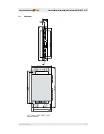
Page 17: ...tice Installation and Operating Instructions ECOVARIO 114 D 17 5 1 2 Dimensions Fig 5 1 Dimensions of ECOVARIO 114 mm upper shield optional 19 mm 245 mm 211 mm 214 mm 279 mm 37 mm 42 mm 323 8 mm 161 mm 165 mm 135 mm 248 mm 265 mm ...

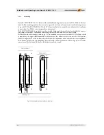
Page 18: ...cables are laid EMC conform by connecting the cable shield extensively to chassis earth The shields with cable clamps shown in fig 5 3 are available as accessories see table 9 1 The lower shield is mandatory the upper shield normally is only necassary if a ballast circuit is connected to X4A and or X4B It is important that the air flow is not disturbed by components above or below the servo amplif...

Page 19: ...e max 10 A Never exceed the maximum rated voltage of 70 VDC 10 at the X4 connector The guarding of the DC supply and the 24 V logic voltage should be carried out by the user Servo amplifier and motor have to be properly grounded The protective earth conductor must have at least the same diameter as the supply cables The servo amplifier should be mounted onto a conductive not var nished metal mount...

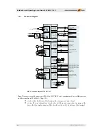
Page 20: ...RS232 Capture 2 8 X22 ASIn1 ASOut1 ASIn2 ASOut2 STO function axis 1 input STO function axis 1 output STO function axis 2 input STO function axis 2 output Reday axis 1 Reset axis 1 X1A X13 X2A X11 X12 CCWI2 Ready2 Reset2 X8 X1B X2B Enable2 DOUT2 Ready axis 2 Reset axis 2 Enable axis 2 X4A VBus VBus PE DC supply SV24 60 60VDC 230VAC 24VDC PE L1 N to other ECOVARIO 114 D X21 CAN 4 CAN Bild 5 4 Connec...

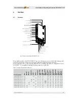
Page 21: ...t X8 Restart lock STO function X1B Digital I O axis 2 X1A Digital I O axis 1 X7A Motor brake axis 1 Order designation CAN EtherCAT Ethernet Profi bus DP RS485 RS232 STO function Encoder input axis 1 Encoder input axis 2 Digital inputs outputs Motor connec tor axis 1 Motor connec tor axis 2 Holding brake axis 1 Holding brake axis 2 DC power supply in DC power supply out ECOVARIO 114DR AJ 000 000 X21...

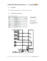
Page 22: ...tal output axis 2 IOmax 0 5 A READY1 3 Ready Digital output axis 1 IOmax 0 5 A RESET1 4 Reset Digital input axis 1 ENABLE1 5 Enable Digital input axis 1 GND24V 6 24 V ground 24V 7 24 V supply logic voltage GND24V 8 24 V ground Fig 6 3 Connector X1A Circuit of the digital inputs and outputs axis 1 2 Fig 6 2 Mating connector X1A FMC 1 5 8 ST 3 81 2CNBD2 ASO 17 03 60 4 Phoenix Load Load Load External...

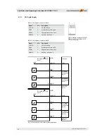
Page 23: ...ital output axis 2 IOmax 0 5 A RESET2 2 Reset Digital input axis 2 ENABLE2 3 Enable Digital input axis 2 24 V IO 4 24 V IO voltage Fig 6 4 Mating connector X1B FMC 1 5 4 ST 3 81 CN3BD2 BSO 17 03 06 5 Phoenix Fig 6 5 Connector X1B Circuit of the digital inputs and outputs axis 2 Load 24 V ECOVARIO 114 D Control RESET Axis 2 ENABLE A 2 1 2 3 X1B READY2 RESET2 ENABLE2 R 4 24V IO 24 V ...

Page 24: ...cription 24 V IO 1 24 V IO voltage CWI2 2 Positive limit switch axis 2 CCWI2 3 Negative limit switch axis 2 HOME2 4 Homing switch axis 2 Fig 6 7 Connector X2A X2B Circuit of the digital inputs Fig 6 6 Mating connector X2A X2B FMC 1 5 4 ST 3 81 2CNBD2 X2SO 17 03 06 6 Phoenix Control ECOVARIO 114 D Axis 1 X2A R 24V Positive Negative limit switch axis 1 limit switch axis 1 Homing axis 1 CWI1 CCWI1 Ho...

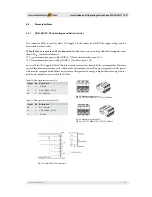
Page 25: ...direct DC supply of the DC link the inrush current is not limited by the servo amplifier Therefore special limitation measures have to be taken in the external power unit If energy is regenerated the power unit must be equipped with a ballast circuit in case the regenerated energy is higher than the energy consu med by all consumers connected to the DC bus Fig 6 8 Mating connector X4IN FKC 2 5 HC ...

Page 26: ...se be connected to the chasis earth or protective earth Due to impro per grounding or free mesh dangerous voltages may occur at the shield Fig 6 11 Mating connector X5A X5B ZEC 1 5 5 ST 5 0 C2 5 R1 5 5BDNZ5 17 55 38 9 Phoenix Signal Keying Pin 2 phase motor 3 phase motor DC Motor Phase A motor U A U 2 Phase A Connection U Conn DC Phase A motor V A V 3 Phase A Connection V Conn DC Phase B motor W B...

Page 27: ...rent consumption of the brake is higher the sta tic version is suitable for connecting a relay cf fig 6 16 Signal Zeichen Pin GND 1 Brake B 2 Imax peak 1 A Imax cont 0 5 A Brake B 3 Table 6 9 Pin assignment connector X7A X7B Fig 6 14 Mating connector X7A X7B ZEC 1 0 3 ST 3 5 C1 3 R1 3 NZX7 19 98 20 5 Phoenix Fig 6 15 Brake connection brake current Imax 0 5 A Fig 6 16 Brake connection brake current...

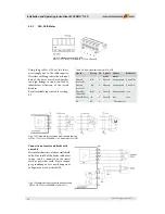
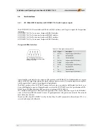
Page 28: ...cording to EN 61800 5 2 or EN ISO 13849 1 The function is established by means of the circuitry shown in Fig 6 18 The signals are lead to the connector X8 Further the signals Enable and Ready of connector X1A axis 1 or X1B axis 2 respectively are used 4 1 Fig 6 17 Mating connector X8 FMC 1 5 4 ST 3 81 CN2BD2 X8SO 17 03 06 7 Phoenix Signal Pin Description STO IN A 1 STO function axis 1 input STO OU...

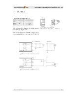
Page 29: ... IN A and Enable channel II software enable is set and the error status of the servo amplifier has been reset The safe status of the restart lock channel I is signalled by the contact between STO OUT A and STO OUT B if the drive is blocked the contact is closed The signal can be fed to a higher level safety PLC and can e g be used for enabling a door lock Channel II If the 24 V voltage is not appl...

Page 30: ...es off the drive because in this case the bridging of the safety equipment is not effective If the restart lock is activated by an automatic control the control signal must be monitored to make sure that the restart lock cannot be activated if the motor is rotating Commissioning and checking the STO function During commissioning of the machine after changing components or restructuring the wiring ...

Page 31: ...n The example in fig 6 20 shows a plant with 2 drives with common power supply The group can be blocked against indeliberate starting via S1 Logic table for FPGA SW Enable STO IN Enable STO OUT Ready 0 H H 0 0 0 H L 0 0 0 L H 0 0 0 L L 1 0 1 H H 0 1 1 H L 0 0 1 L H 0 0 1 L L 0 0 Fig 6 20 Example for STO function ...

Page 32: ...signal up to 99 are possible λd t b d 10 8 6 5 Encoders The servo amplifier ECOVARIO 114 D has one encoder input for each axis X11 for axis 1 and X12 for axis 2 Never plug and pull encoder cables while they are live Always switch off the logic supply of the ECOVARIO Otherwise damages to the encoder can occur Encoder inputs X11 X12 Apart from incremental standard encoders also absolute value encode...

Page 33: ...sor 11 B Track B B Track B Z Track N 12 VENCSENSE Sensor UP VENCSENSE Sensor UP VENCSENSE Sensor UP VENCSENSE Sensor UP 13 B Track B B Track B Z Track N 14 A Track A A Track A CLK CLK 15 A Track A A Track A CLK CLK the same supply voltage for both encoders Connection of a second incremental or JAT SinCos encoder via Y cable If required a further incremental or SinCos encoder can be connected to th...

Page 34: ...tructions ECOVARIO 114 D 34 Subject to change without notice Fig 6 23 Example for connection for a 5 V incremental encoder SinCos encoder deviations in brackets Fig 6 24 Example for a BISS encoder via standard cable ABS65 300 525 xx ...

Page 35: ...Temperature sensor DGND 6 Encoder ground A 7 Track A B 8 Track B N 9 Track N Table 6 19 Pin assignment connector X11 X12 Mating connector X11 X12 9 pole Sub D connector view of the solder or crimp side Fig 6 29 Example for connection for 5 V incremental encoder with standard cable INK65 491 525 xxx The supply voltage UP of the encoder is 5 V The maximum cable length is 50 m The maximum signal freq...

Page 36: ...he capture inputs are not galva nically separated and can also be configured as digital inputs The RS485 interface of the ECOVARIO may as well serve for a 4 conductor full duplex as also a 2 con ductor half duplex connector Transmitter and receiver of the ECOVARIO meet the specifications of EIA RS485 up to 250 kBaud and are EMC protected according to IEC 61000 4 4 The communication protocol allows...

Page 37: ...tice Installation and Operating Instructions ECOVARIO 114 D 37 Fig 6 25 Example for connection RS485 point to point connection in half duplex mode Fig 6 26 Example for connection RS485 point to point connection in full duplex mode ...

Page 38: ...hat a 1 1 standard cable for communication with a COM port 9 pole Sub D connector can be used Transmitter and receiver of the ECOVARIO 114 D meet the specifications of EIA 232E and CCITT V 28 and are EMC protected according to IEC 61000 4 2 The communication protocol allows net work operation of up to 126 ECOVARIO units as slaves in a mono master network For this option a ring structure of the RS2...

Page 39: ...e without notice Installation and Operating Instructions ECOVARIO 114 D 39 Fig 6 29 RS232 network in ring structure Fig 6 30 RS232 cable ECOVARIO PC view of the solder or crimp side of the plug connectors at the cable ...

Page 40: ...e potential to CAN_V 7 CAN_H CAN data H 8 n c 9 CAN_V 12 VDC 4 VDC max 50 mA Table 6 18 Pin assignment connector X21 Fig 6 32 Circuit X21 design with CAN interface The manual Object Dictionary ECOVARIO ECOSTEP ECOMPACT ECOMiniDual contains a detailed descrip tion of all available functions The Baud rate und the device ID can be set with the front keys of the device see chap 7 3 3 Key operation or ...

Page 41: ...g options ECOVARIO 114 Dx F x xxx xxx CAN RS485 PROFIBUS DP V0 ECOVARIO 114 Dx G x xxx xxx CAN RS232 PROFIBUS DP V0 ECOVARIO 114 Dx L x xxx xxx CAN RS232 Ethernet interface ECOVARIO 114 Dx P x xxx xxx CAN RS485 EtherCAT interface ECOVARIO 114 Dx Q x xxx xxx CAN RS232 EtherCAT interface Fig 6 32 size terminating resistors R acc to line impedance normal R 120 Ω ...

Page 42: ...to 32 participants master or slaves can be connected Each segment has an active bus terminating module at the beginning and at the end cf Fig 6 35 To obtain faultless operation it has to be made sure that both bus terminating modules are continuously supplied The bus terminating module is commonly realized in the bus connectors to be switched in If there are more than 32 participants or for enlarg...

Page 43: ...e possibility to connect incoming and outgoing cables directly in the connector Thus spur lines are avoided and the bus connector can be plugged in and off the bus without interrupting the data transmission Use only bus connectors suitable for PROFIBUS DP V0 and the respective baud rate The connectors at both ends should provide a termination to be switched in Additionally in each connector should...

Page 44: ... only necessary if a communication to external network is intended to be set up The interfaces X22A and X22B are each equipped with the following display elements green LED displays Link Activity orange LED displays Collision Detection An ECOVARIO which is operated with the Ethernet interface automatically selects the interface used for message transfer If a CAN bus connection is available all mes...

Page 45: ...transport via Ethernet The original CAN data is extracted from these packages and is lead to the CAN bus All bus nodes also the ECOVARIO with Ethernet interface can receive them In the other direction all CAN messages received via the bus are pa cked into UDP packages and sent via the Ethernet The Ethernet function supports full SDO transfer with one or more client applications on PC IPC side The ...

Page 46: ... via the CAN bus The SDO transfer with the PC IPC does not reach the CAN bus which is not disturbed e g synchronous motion In order to change the operation mode the gateway mode has to be deactivated in each device object 0x2FB2 sub index 12 because otherwise the devices would send the messages to each other continuously Process data communication is decoupled completely from the Ethernet in this ...

Page 47: ... are possible as well The cable length between two devices is limited to 100 m For process control and visualization of EtherCAT devices the operation with the PC software TwinCAT manufacturer Beckhoff GmbH is proposed For configuration instructions and an application example please refer to Application Note 26 The objects which are required for the configuration of the EtherCAT communication are ...

Page 48: ...re managed Parallel operation In principle CAN and EtherCAT can be operated in parallel cf Fig 6 40 where the CAN bus is used for parame terization while EtherCAT is used for the synchronous interpolated operation As soon as the ECOVARIO has been configurated successfully by the EtherCAT master and has been set to preoperational state via EtherCAT the NMT telegrams via CAN are ignored PDOs assigne...

Page 49: ... one axis after the other The axes already commisioned should be switched off For commissioning of the safety function STO observe chap 6 4 1 During operation the temperature of the heat sink and the housing may rise up to over 70 C Before touching these parts after switching off the unit wait until the temperature has fallen down to 40 C 7 2 Control and display elements At the front side of the E...

Page 50: ...echanical configuration must be adjusted to each specific case Incorrect parameter settings can cause damage or destruction of machine parts With the help of the ECO Studio device configuration wizard and of the mechanical configuration wizard carry out the basic settings for the operation of ECOVARIO A detailed description of software commis sioning can be found in the ECO Studio Operation Manual...

Page 51: ...lashes Display shows Active state power stage switched on at both axes display 8 dot flashes Blocking Display shows positive limit switch axis 1 reached Display shows negative limit switch axis 1 reached Display shows both limit switches axis 1 reached Display shows positive limit switch axis 2 reached Display shows negative limit switch axis 2 reached Display shows both limit switches axis 2 reac...

Page 52: ...tchdog error of standard loadware If the error reoccurs send in the device to manufacturer A24 Firmware Loadware does not fit to device Load appropriate firmware loadware First letter of the file name has to be D If in doubt contact service hotline of Jenaer Antriebstechnik GmbH A25 FPGA could not be started A26 Device could not be started Contact service hotline of Jenaer Antriebstechnik GmbH Gro...

Page 53: ...erconnection Gruppe E Encoder errors The error code on the display is preceded by an axis code 1 or 2 E00 Antivalence error of 1st incremental encoder of the axis or No encoder has been selected however the power stage is switched on Check encoder and supply cables for wire breakage If no encoder is configurated select encoder Check whether the correct encoder port has been selected In case of ext...

Page 54: ...mmunication settings of the device ID and the CAN baud rate can be made with the keys on the front of the device Furthermore Ethernet IP or EtherCAT addresses can be retrieved Functions of the keys Key S1 select menu navigation count up display values Key S2 enter select menu option accept values Fig 7 1 Work schedule key operation ...

Page 55: ...n the bootloader mode only error messages of group A are displayed During saving data in the EEPROM the display shows a P Afterwards the prior value is displayed 8 Parameter setting By setting the parameter the ECOVARIO 114 D is adjusted to the application The parameters are set in the PC The user interface ECO Studio is menu driven and easy to handle There are several interfaces to connect the PC...

Page 56: ...ftware tools and documentation ECO2CD CD with ECO software tools and documentation Power supplies SV24 1 phase power supply 24 VDC 5A SV24 60 1 phase power supply 24 VDC 2A 60 VDC 5A SV60 1 phase power supply 60 VDC 5A Cables INK65 491 525 xxx Encoder cable for motors with incremental or SINCOS encoder ABS65 300 525 xxx Encoder cable for motors with BiSS encoder MOT43 132 721 xxx Motor cable exten...

Page 57: ...erally required For mounting a shield plate proceed as follows 1 On the respective side of the servo amplifier loosen the screws Pos 1 and screw them approx 2 mm out 2 Shift the shield plate with the cutout Pos 2 under the screw heads Pos 1 and into the studs on the side of the servo amplifer Pos 3 3 Tighten the screws Pos 1 again The fixing of the cables can be achieved by cable ties and shield c...

Page 58: ...ld mesh of the cables must be connected to the device potential or the PE conductor resp If the grounding is improper or the mesh lies freely dangerous voltages may occur The following table lists the cables available for connection of the motors of Jenaer Antriebstechnik GmbH If other cables are used functional errors of the drive and EMC problems might occur If you intend to use other cables ple...

Page 59: ...e of the servo amplifier in which a new loadware can be transmitted into the servo amplifier s memory Brake chopper The brake chopper circuit produces a high inrush current that initiates a quick pulling of the brake After pulling the brake the current is reduced to a lower holding current Capture input Control input for quick event capture of a machine or plant Circuit breaker Switch that cuts th...

Page 60: ... events is defined de pending on external states input data internal states actual values or time states Short circuit Here electrically conductive connection between two power systems or motor phases STO function Safe Torque Off safety function defined in EN DIN 61800 5 2 The motor is not supplied with energy and cannot generate a rotation The STO function is used for the implementation of the re...

Page 61: ...ISO 12100 1 Safety of machinery Basic concepts general principles for design Part 1 Basic terminology methodology DIN EN ISO 12100 2 Safety of machinery Basic concepts general principles for design Part 2 Technical principles DIN EN ISO 13849 1 2006 Safety of machinery Safety related parts of control systems Part 1 General principles for design IEC 61000 4 2 Electromagnetic compatibility EMC Part ...

Reviews: