Installation and Operating Instructions ECOVARIO®114 D
38
Subject to change without notice!
Design with RS232 interface
Apart from the serial interface the connector X13 of the ECOVARIO®
114 D provides two capture inputs with RS422 signal transmission for
rapid event capture.
Alternatively to the USB interface, via the RS232 interface a PC can be
connected for setting the parameter of the ECOVARIO® 114 D. How
to set the parameters of the RS232 interface is described in the manual
„Object Dictionary ECOVARIO®, ECOSTEP®, ECOMPACT®, ECO-
MiniDual“.
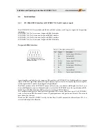
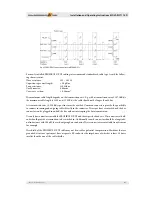
For RS232 communication with
ECOVARIO® 114 D a 3-core connection to
the host is needed. Th e connector X13 of the
ECOVARIO® 114 D is designed in a way
that a 1:1 standard cable for communication
with a COM port (9-pole Sub-D connector)
can be used. Transmitter and receiver of the
ECOVARIO® 114 D meet the specifi cations
of EIA-232E and CCITT V.28 and are EMC-
protected according to IEC 61000-4-2.
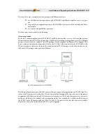
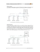
Th e communication protocol allows net-
work operation of up to 126 ECOVARIO®
units as slaves in a mono master network.
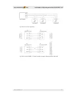
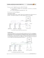
For this option a ring structure of the RS232
network according to the scheme in fi g. 6.29
is necessary.
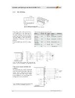
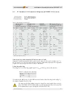
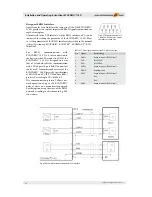
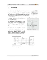
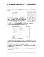
Fig. 6.27: Mating connector X13:
9-pole Sub-D connector, view of
the solder or crimp side
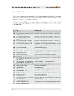
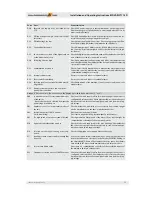
Pin
Signal
Beschreibung
1
CAP1+
Capture input 1 (RS422 level)
2
TxD
RS232 TxD
3
RxD
RS232 RxD
4
CAP2+
Capture input 2 (RS422 level)
5
DGND
Digitalground
6
CAP1-
Capture input 1 (RS422 level)
7
-
free
8
-
free
9
CAP2-
Capture input 2 (RS422 level)
Table 6.17: Pin assignment connector X13 in RS232 design
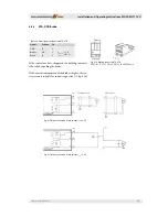
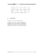
Fig. 6.28: Example for connection of an RS232 interface

