Installation and Operating Instructions ECOVARIO®114 D
44
Subject to change without notice!
6.8.3
X22: Designs with Ethernet interface
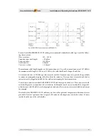
As an option, ECOVARIO® can be equipped with an Ethernet interface which can be used for parameteri-
zation. Th e interface supports Fast Ethernet according to IEEE-802.3u (100Base-TX), halfduplex, 100Mbps.
Physically, the interface is designed as two standardized RJ45-sockets at the front side of the ECOVARIO®.
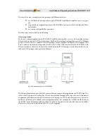
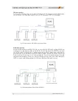
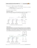
Th e interfaces X22A and X22B can each be used for the connection to the PC or a server (end of a star-
shaped connection) as well as for the connection to further servo amplifi ers via a line-shaped connection
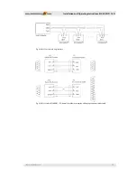
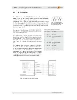
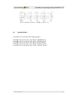
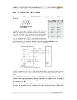
(uplink, cf. examples below).
Cabling is done via twisted-pair-cables UTP, Cat.5e. Star and line topologies are supported. Not more than
6 ECOVARIO® servo amplifi ers should be cabled in line. Th e cable length between two devices is limited to
100 m.
For using the Ethernet interface the IP address, the subnet mask, the port and, if necessary, a gateway IP
address have to be parameterized. Th e gateway IP address is only necessary if a communication to external
network is intended to be set up.
Th e interfaces X22A and X22B are each equipped with the following display elements:
green LED displays „Link Activity“
orange LED displays „Collision Detection“.
An ECOVARIO® which is operated with the Ethernet interface automatically selects the interface used for
message transfer. If a CAN bus connection is available, all messages which the ECOVARIO® intends to
transmit, e.g. PDOs, emergencies or the boot-up message are sent on the CAN bus. If no CAN bus voltage
can be detected it is assumed that a pure Ethernet application is set up and all messages are sent via Ethernet
(if no Ethernet cable is plugged, the messages are lost!). CAN bus has the highest priority, i.e. the messages
are transmitted via CAN bus as soon as the CAN connector has been plugged. Ethernet messages are not
sent until 5s aft er power-up, because the hardware requires this time for confi guration. During this time up
to 8 (via DPM) or up to 32 (via CAN-Bus) received messages are stored temporarily.
Pin
Signal
Description
1
RX+
Receive
2
RX-
Receive signal -
3
TX+
Transmit
4
-
n.c.
5
-
n.c.
6
TX-
Transmit signal -
7
-
n.c.
8
-
n.c.
Table 6.20: Pin assignment connector
X22A,B on design with Ethernet interface

